12 Procedure for Receiving a Replacement Device
SMA Solar Technology AG
Operating manual STP15-25TL-30-BE-en-17 81
• Position the upper enclosure lid with the six
screws and conical spring washers on the
enclosure and tighten it using an Allen key
(AF4) in the order 1 to 6 (torque: 6Nm ±
0.3Nm).
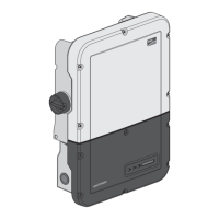
5. Insert the lower enclosure lid from above and flip it down. Use the enclosure lid of the
defective inverter for this if there is a label with "transport lid" affixed to the enclosure lid of the
replacement device. The screws must protrude from the lower enclosure lid.
6. Tighten all six screws of the lower enclosure lid
using an Allen key (AF3) in the order 1 to 6 (torque:
2.0Nm ± 0.3Nm). By tightening the screws in the
prescribed order, you avoid warping the lid, which
would keep it from sealing correctly. Tip: If the
screws fall out of the lower enclosure lid, insert the
long screw into the lower middle hole and the five
short screws into the other holes.
7. Recommission the replacement device (see Section7.3, page42). Remount the DC load-
break switch of the defective inverter to the replacement device.
8. Configure the replacement device (see the operating manual of the inverter).
9. Replace the replacement device in the communication product.
Shipping the Defective Inverter
1. If necessary, position the upper enclosure lid with
the six screws and conical spring washers on the
enclosure and tighten it using an Allen key (AF4) in
the order 1 to 6 (torque: 6Nm ± 0.3Nm).
2. Insert the lower enclosure lid from above and flip it down. The screws must protrude from the
lower enclosure lid.

 Loading...