Route communication cable
The EV Wall requires a communication cable between the EV Wall and the distribution panel where
the CT measurements and Connect gateway are placed. To do this, two twisted pairs of a Cat 5 or
Cat 6 networking cable are used. The Cat 5/6 cable should be connected between the PCB of the EV
Wall’s front plate and the splitter in the distribution panel. An RJ-45 connector (not supplied) should
be attached to both ends of the cable. Only attach the RJ-45 connector after inserting the cable into
the housing. The RJ-45 connector will not fit through the EV Wall’s cable gland!
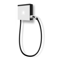
Prepare the mounting
All Smappee EV Wall types are designed to be mounted on a wall.
When positioning the EV Wall, take into account that the power supply cables and communication
cable are entering the housing at the bottom through cable glands. The central M32 cable gland is
for the power supply, the M20 cable gland for the communication cable.