Installation
1. Read the instructions carefully.
2. Install a 240V, adequately protected 3-pin socket near
where the Smart Slider opener is going to be installed
3. Make sure the gate and fence structure is solid and
suitable to be motor driven. A strong base on the gate
is required for securing the rack and an appropriate
concrete slab or similar surface for the Smart Slider
opener.
4. Make sure that when the gate is moving there are no
friction points.
5. The gate must be properly balanced and must be
easily moved by hand..
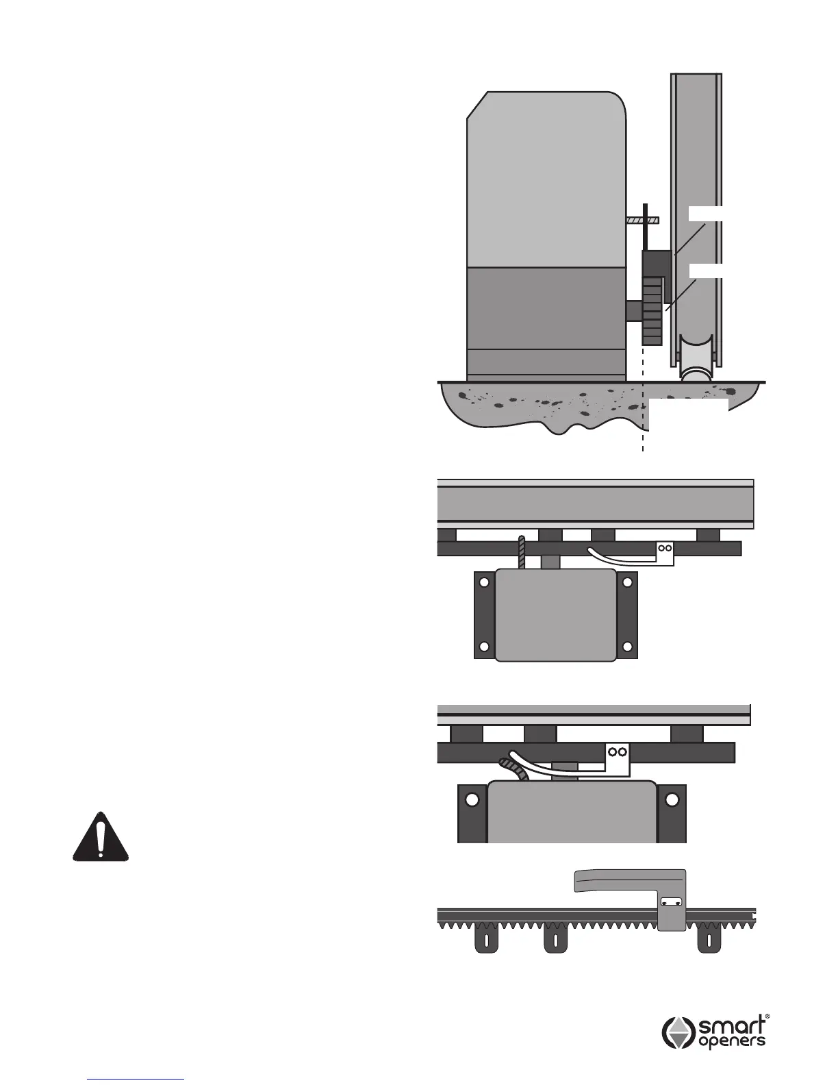
Positioning The Opener
1. Measure the width of the rack (Smart Openers rack is
40mm) If using third party rack make sure it is Module 4.
2. Move the gate to the desired open position. Position
the opener approximately 150mm from the leading
edge and parallel to the gate and make sure that the
pinion gear is aligned with the rack (Fig. 1).
3. Mark the position of the xing holes and secure with
8mm or 10mm loxins or dynabolts (Fig. 2).
Fixing The Rack
1. With the gate in the desired open position place a
section of rack to mesh with the pinion gear and mark
the xing holes. The rack should start about 25mm
from the edge of the gate (Fig. 2).
2. Repeat the above for the entire length of the gate.
3. Ensure that all rack sections mesh together for
smooth operation.
Fixing The Limit Cam
1. Disengage the opener by releasing the key latch and
moving the manual release arm out at a 90° angle.
2. Move the gate to the desired open position. Place a limit
cam on the rack so that it just triggers the limit switch.
Make sure the cam is facing toward the opener, not
away (Fig. 3).
3. Mark this position and secure the limit cam to the gate
rack.
4. Move the gate to the desired closed position and
repeat as above. Make sure the cam is facing toward
the opener, not away.
WARNING: Make sure the gate has
mechanical stops tted to prevent
the gate rolling out of its guides
when in manual operation. Failure to follow
this warning may result is serious personal
injury and/or property damage.
Antenna
The Smart Slider’s RF receiver features an integrated
antenna in the receiver board. There should be no need
for an external antenna.
Fig. 1
Fig. 2
RACK
PINION
ALIGN TEETH
OF PINION
AND RACK
Fig. 3
-7-
© March 2008 Smart Openers Pty Ltd