5
4
2
1
3
3
System Description
FRONT PANEL
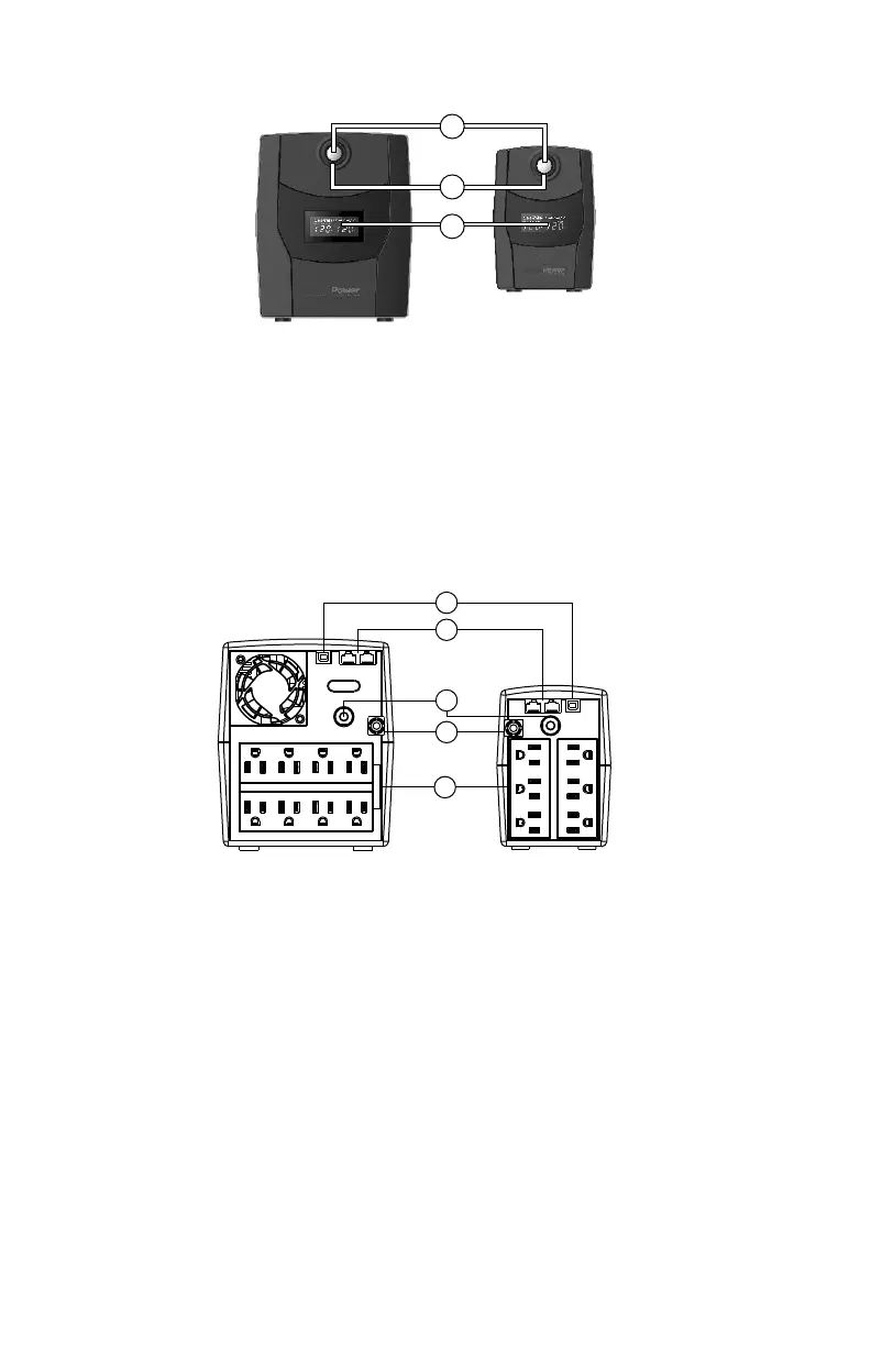
BACK PANEL
1.USB Port
This port allows connection and communication from the USB port on the computer to the UPS.
The UPS communicates its status to the Power Master software.
2.Communication Protection Ports
Communication protection ports will protect any standard modem, fax, telephone line, or network cable.
3.Input Circuit Breaker
The circuit breaker provides overload protection.
4.Input Power Cord
Connect to utility power.
5. Battery Backup & Power Conditioning-Protected Outlets
Provides battery backup and surge protection. They ensure power is provided to connected equipment
over a period of time during a power failure.
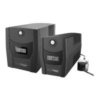
1.LCD Display
The LCD will display the UPS status including input voltage, output voltage, runtime, percentage
of load and battery etc.
2.Power On/Off Switch
Press the power switch to turn the UPS ON or OFF.
Press the power switch 2 times to disable and enable the alarm beeping sound.
3.Led Indicators
This LED is illuminated when the UPS is ON.
1
3
2
 Loading...