5 Installation Continued
Never touch the power switch with wet hands to avoid electrical shock.
Do not touch the surface when the set temperature is high. Temperature
of the tank and the chassis near the tank could be high.
Fluid other than water or Ethylene Glycol (up to 20%) should not be
used as circulating fluid. Using such fluid may lead to leakage or
damage of the pump.
Operation of the pump with a large amount of air left in the piping for
prolonged period may damage the pump. Remove air from piping before
starting operation.
If the power switch is turned on without circulating fluid, the pump could
be damaged.
Take care not to spill water over the product when supplying water to the
reservoir. When a spill is made, wipe it off immediately and only supply
power after it has dried. If this procedure is neglected, it may cause
damage to the product.
If a fluid with low conductivity such as DI water is used as circulating fluid,
it can cause static electricity due to friction and damage the product.
Take measures to minimize the static electricity from circulating fluid.
If the product is operating for a long time with large temperature
fluctuations after reaching the set temperature, the product may be
damaged. Please set the PID values by using the auto-tuning function.
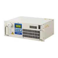
6 Operation
6.1 Power Up
When power is turned on, the software version is indicated on display
panel for approx. 1 second.
6.2 Operation
The product begins operation immediately after the power is turned on.
The pump and heat exchanger will be running and the product will begin
temperature control.
The display can show the following information during operation.
6.3 Settings
Three different levels of settings are available
depending on the content, which needs to be set.
Level 1: Used in normal operation e.g. setting
of target temperature and offset.
Level 2: Used at maintenance and initial setting
for setting of controller/PID.
Level 3: Used at initial setting for the
communication function.
The key functions are as follows:
[SEL]: Used to show the item that needs to be
changed in selected mode level.
[▽△]: Used to change the value of the item selected.
[RET]: Used to fix the value changed by [▽△] key.
Press again to return to current temperature
indication.
[AT]: Used to start auto tuning in auto tuning mode
(This function works when the control operation mode is 2 in level setting 1)
When pressed during auto tuning, the auto tuning is stopped.
When no input is made within 1 minute regardless of setting mode, the
display returns to the current temperature indication.
The data input is written to FRAM and memorized after the power supply
is turned off.
To return all of the setting values to default: Turn on the power supply
while pressing [SEL] and [RET] keys.
6 Operation Continued
6.3.1 Level 1-Settings
Setting range
(Min. increment)
Target Temp.
(No indication on
display)
Sets target temp. for control.
Selects control operation mode
from those shown below.
0: Pump stop (No control)
1: Normal operation
2: AT(auto tuning)
3: Learn (learning control)
4: External (external tune control)
5: SeriRem (Serial remote)
5:Serial remote is displayed when
choose the Modbus
communication.
External Sensor
Sampling Cycle
Sets sampling cycle for learning
control or external tune control.
Indicates the offset value of the
circulating fluid temperature used
as reference value by the
controller (SV + Offset).
Allowable Upper
Temp. Range
Sets upper limit of temp. range
which causes a warning to occur.
Allowable Lower
Temp. Range
Sets lower limit of temp. range
which causes a warning to occur.
Sets upper limit of temp.
measured by the internal temp.
sensor and stops operation of the
product.
Sets lower limit of temp. measured
by the internal temp. sensor and
stops operation of the product.
Setting range
(Min. increment)
Fine Control of
Internal Sensor
Sets the fine adjusting value to
calibrate the internal temp.
sensor
Fine Control of
External Sensor
Sets the fine adjusting value to
calibrate the external temp.
sensor available optionally.
Sets PB (Proportional Band)
range used for PID control.
Sets integral time used for PID
control.
Sets differential time used for
PID control.
When 0 is set, differential
operation is not made.
Sets output ratio of cooling to
heating to compensate
difference of gain between them.
Overload Judging
Temp. Rang
Sets the temp. range for
judgment of overload
(accompanying abnormal output
alarm ERR15).
Sets time for judgment of
overload (accompanying
abnormal output alarm ERR15).
When 0 is set, the alarm doesn’t
arise.
Shows output ratio of thermo
module by 1%. The prefix
symbol “-” stands for cooling and
no prefix stands for heating.
Upper/Lower
Temp. Alarm
Sequence
Determines whether or not temp.
upper/lower limit alarm is output
when power is turned on.
On : Output
Off : Not output
Sets the termination resistor (120
) for RS-485 communication
Set the Communication protocol.
SMC CMD:same as existing HEC
communication
Modbus:Modbus communication
Sets the unit No. used. This is
applicable only when multiple
Thermo-cons are used.
(Unit number 1 to F is vaild when
used the Modbus communication)
Sets baud rate for
communication.
600, 1200, 2400,
4800, 9600,
19200b/s
Sets parity bit for communication.
None : No parity
Odd : Odd
Even : Even
Sets data length for
communication.
Sets stop bit for communication.
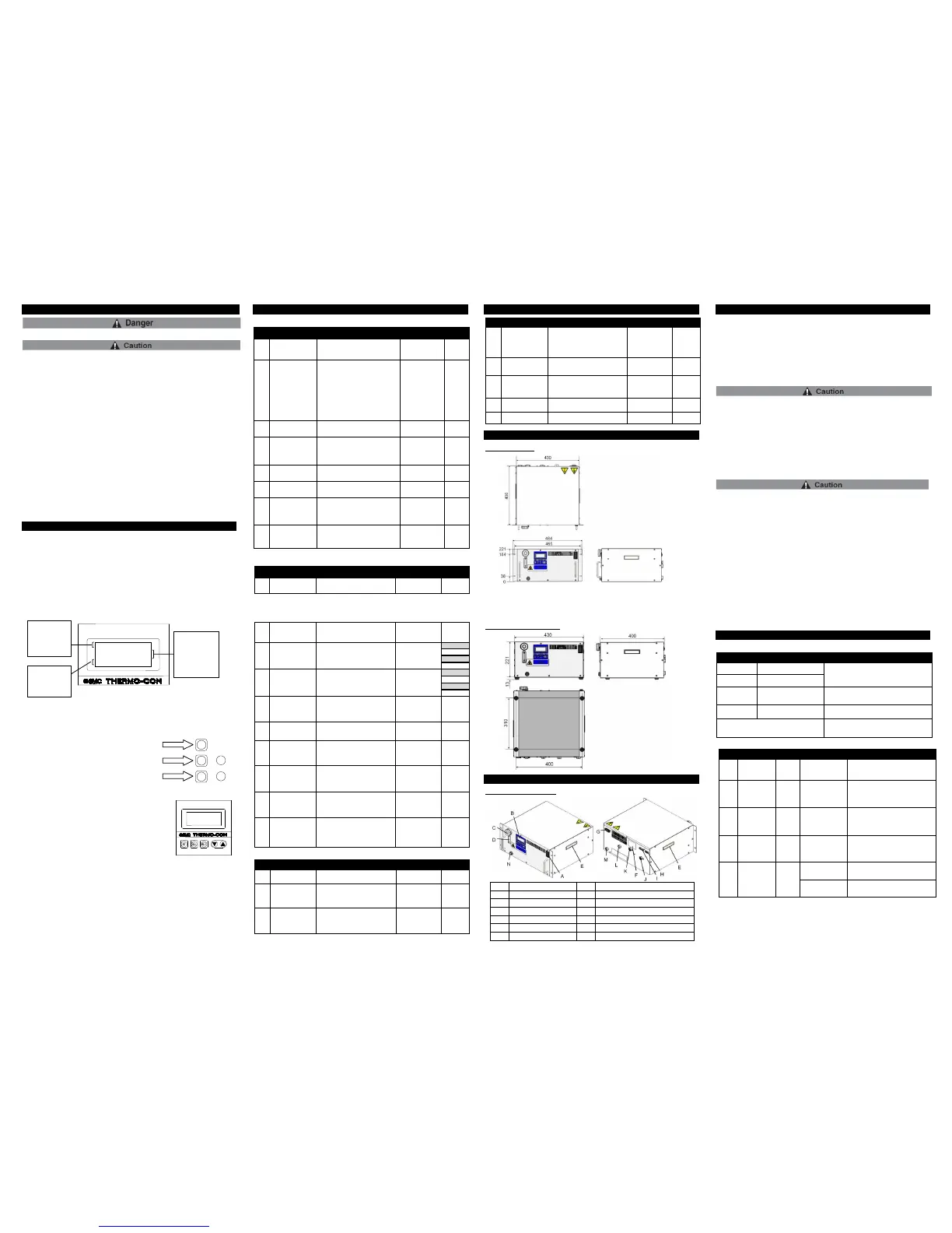
7 Outline Dimensions (mm)
HECR008/012-W
HEC008/012-W-E(option)
8 Key Parts
HECR008 / HECR012-W
9 Maintenance
9.1 Daily Check
1) Indication of display panel: Check temperature condition and confirm
whether or not an alarm has occurred.
2) Confirm that the panel are free from dust. A large amount of dust may
impair the performance.
3) Confirm there is no leakage of circulating fluid and check the condition
of the piping (e.g. no tight bends or crushed pipes).
4) Confirm there is no abnormal sound, smell or heating from the product.
When cleaning the panel use a vacuum cleaner to remove the dust. Do
not use water or steam since it leads to rusting of the frame.
9.2 General Maintenance
Replace the circulating fluid regularly to avoid any problems due to algae
or contamination.
<Drain circulating fluid>
1. Drain circulating fluid from the Drain port.
Loosen the reservoir cap to help draining. (Do not remove the cap)
2. To drain from the piping, blow air (0.1MPa, about 1 minute) from Fluid
OUT to Drain port. Close the reservoir cap and Fluid IN while blowing.
The repair and maintenance services of this unit are performed only at
SMC factory. SMC does not provide on-site repair or maintenance
service in a national or overseas situation.
It is recommended to prepare spare units to minimize downtime due to
those repair and maintenance services.
Drain the fluid from the product when it is returned for the repair and
maintenance service. If the fluid is left inside, an accident and damage
can result during transportation.
Do not make any modification to the product.
Do not disassemble the product, unless required by installation
instructions.
If fluid other than water is used, wash the circulating fluid circuit with
water or DI water before returning the product to SMC. Products that
have not been washed may not be accepted at the factory.
10 Troubleshooting
10.1 How to reset the alarm
Restart the power supply. In the case the
alarm can’t be reset by above manner, repair
is required.
Initialization of FRAM or stop and restart of
power supply In the case the alarm can’t be
reset by above manner, repair is required.
Temp. upper/lower limit
alarm
The unit continues controlling and recovers
normal condition at any time.
Remove a possible cause and restart. In the
case the alarm can’t be reset by above
manner, repair is required.
Fluid temperature is
out of limit range.
Product is reaching target temperature.
Wait for the temperature to stabilize,
then the WRN should disappear.
The wire inside the
Thermo-con was
broken due to
vibration during
transport.
In the case the alarm can’t be reset by
above manner, repair is required.
The FRAM data was
destroyed by high-
level noise.
Move the product to an environment
with little noise, turn ON the power
supply. If there is no alarm, it was
caused by noise.
Please consult with SMC.
The memory data
was destroyed by
high-level noise.
Move the product to an environment
with little noise, turn ON the power
supply. If there is no alarm, it was
caused by noise.
Please consult with SMC.
DC output voltage of
product is reduced.
Check the power voltage.
HECR008: 100 to 240VAC
HECR012: 200 to 240VAC
The fans at the
power supply stops.
Remove foreign matters which might
stop the fan.
2nd, 3rd line
Current temp.[PV]]and
target temp.[SV] during
normal operation.
When the alarm arises,
the error is indicated
instead and during
setting mode selection,
the selected setting
mode is indicated.
1st line
Indicates No.
corresponding to the
alarm which arises and
[WRN] comes to light
up when temp. upper
or lower limit warning
occurs.
4th line
Indicates control
operation mode
during normal
operation and set
values during setting
mode selection.
ERR11 WRN
PV < 31.6 °C #1
SV < 30.0 °C
MODE Normal
External sensor/Alarm output connector
 Loading...


