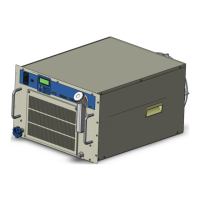
Do you have a question about the SMC Networks HRL100-A 40 Series and is the answer not in the manual?
| Brand | SMC Networks |
|---|---|
| Model | HRL100-A 40 Series |
| Category | Chiller |
| Language | English |
Provides essential safety guidelines and precautions before operating the product.
Explains the use of symbols in the manual to highlight important actions.
Details the levels of hazards, including definitions for serious and minor injuries.
Information on how to identify the product's model and serial number from its label.
Covers safety instructions for use and specifies required personal protective equipment.
Describes emergency procedures to be followed in case of incidents like fire or earthquake.
Provides instructions for the proper disposal of refrigerants, compressor oil, and the product.
Information on obtaining safety data sheets for chemicals used in the product.
Explains how the product model number is configured and its importance.
Details the names and functions of various parts for air-cooled and water-cooled types.
Provides a detailed table listing parts and their specific functions.
Covers safe transportation methods, including using forklifts, hanging, and casters.
Details installation requirements, including environment, location, and space considerations.
Explains the physical installation process, including using brackets and adjuster feet.
Provides critical safety warnings and instructions for electrical wiring.
Details the procedures for preparing and wiring the power supply cable safely.
Explains the product's contact input/output communication capabilities and connectors.
Details the wiring procedures for analog output signals and their specifications.
Provides information on RS-485 communication, including connector specifications.
Explains RS-232C communication wiring and connector details.
Details Ethernet Modbus/TCP communication wiring and connector specifications.
Provides CAUTIONary advice on connecting piping and material selection.
Instructions for supplying circulating fluid, including filling levels and water quality.
Lists essential checks to perform before starting the product operation.
Covers power supply activation and the initial startup screen sequence.
Guides on supplying additional circulating fluid to the product and user's equipment.
Details on setting fluid temperature, pump mode, starting, and stopping the product.
Lists items to check after the product has started operation for abnormalities.
Guidance on adjusting circulating fluid flow rate for optimal performance.
Introduces basic operations controlled via the product's touch panel.
Illustrates the flow between different operation screens on the touch panel.
Provides a comprehensive list of product functions and their corresponding outlines.
Detailed explanation of the home screen elements and their functions.
Explains how to access and navigate the main menu on the touch panel.
Describes the status screen, which displays sensor values and operating conditions.
Details the information screen for viewing alarms, maintenance reminders, and history.
Shows how to check component operating times and maintenance reminders.
Explains how to view the product's software version and program details.
Covers settings for CH1, including alarms, TEMP READY, and pump operation.
Covers settings for CH2, including alarms, TEMP READY, and pump operation.
Details various functions like KEY-LOCK, ANTI-FREEZING, and alarm settings.
Explains settings for communication errors, input/output signals, and serial/Ethernet.
Provides instructions on how to configure the product's IP address for network settings.
Describes the temperature waveform screen for monitoring temperature trends.
Details the specifications and features of the CH2 high-pressure pump option (T2).
Details the specifications and features of the CH2 high-pressure pump option (T3).
Explains how the product notifies users of alarms and their content.
Describes how the product operates differently based on alarm content (continuation/stop).
Guides users on how to troubleshoot alarms based on their codes and causes.
Addresses failures that occur without specific alarm codes being displayed.
Specifies quality criteria for circulating and facility water to prevent issues.
Covers daily, monthly, 3-month, and 6-month inspection and cleaning procedures.
Provides instructions for safely stopping the product for extended periods or winter storage.
Details the procedures for replacing consumable parts like particle filters and DI filters.
Lists detailed technical specifications for various product models (A and W series).
Provides dimensional drawings and anchor bolt positions for different models.
Illustrates the flow diagrams for air-cooled (A) and water-cooled (W) product types.
Presents cooling capacity charts for different models and options under various conditions.
Shows pump capacity curves (pressure vs. flow rate) for various models and options.
Explains the warning labels used on the product to indicate potential dangers.
Lists the standards and directives that the product complies with.
Provides a template for recording daily checks and the product's condition.
Defines the warranty period for the product.
Outlines the scope of the warranty, including what is covered and excluded.
Specifies the guarantees provided by SMC regarding product operation and quality.
Addresses resolving doubts regarding warranty scope and contents through agreement.
Lists expenses and conditions not covered by the warranty or agreement.
Emphasizes proper use and maintenance as preconditions for warranted repair.
Explains the procedure for requesting warranted repair services.


 Loading...