HRX-OM-X037
Chapter 2 Name and Function of Parts
HRL Series 2.3 Function of Parts
2.3 Function of Parts
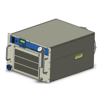
The function of parts is as follows.
Table 2.3-1 Function of parts
Operational settings for the product. Example: Run and stop product.
Performance setting
Indicates the circulating fluid level of the tank. Confirm the level is
between HIGH and LOW. For details, refer to “3.5 Circulating Fluid Supply”.
Shows the product information, such as model number and serial
number. For details, refer to ‘’1.4 Product Label’.
Circulating fluid
outlet port (CH1)
The circulating fluid flows out from the outlet port.
For laser source.
Circulating fluid
outlet port (CH2)
The circulating fluid flows out from the outlet port.
For optical systems.
Circulating fluid
return port (CH1)
The circulating fluid returns to the return port.
Circulating fluid
return port (CH2)
This drain port to drain the circulating fluid out of the tank.
Inserted to prevent dust and contamination clinging to the air cooled
condensers directly.Clean the filter periodically.
For details, refer to “8.2.2 Monthly check”.
Insert the power cable to the power cable entry and connect it
to the power terminal. For details, refer to “3.3.2 Electrical wiring”
and “3.3.3 Preparation and wiring of power supply cable”.
Insert the signal cable to the signal cable entry and connect it to
the signal connectors. For details, refer to “3.3.5 Wiring of the Run/Stop
signal input”, “3.3.6 Wiring of the contact output signal”, “3.3.7 Wiring of
analog output signal”,“3.3.8 RS-485 communication wiring”,
“3.3.9 RS-232C communication wiring” or the Operation
Manual Communication Function.
Earth leakage breaker
/ Breaker handle
Shuts off the power supply to the internal equipment of the product.
(Parts energized remained in the product.)
Refer to “3.3.2 Electrical wiring” for the earth leakage breaker.
Supply circulating fluid to the tank.
Facility water inlet
(For Water-cooled
type)
A facility water inlet to which the facility water is fed through piping.
The pressure of facility water should be in a range of 0.3 to 0.5MPa.
Facility water outlet
(For Water-cooled
type)
A facility water outlet from which the facility water returns to the user’s
machine through piping.

 Loading...


