HRX-OM-X037
Chapter 9 Documents
HRL Series 9.4 Cooling Capacity
9.4.3 HRL300-A-40 CH1
Fig. 9-9 Cooling Capacity (HRL300-A-40 CH1)
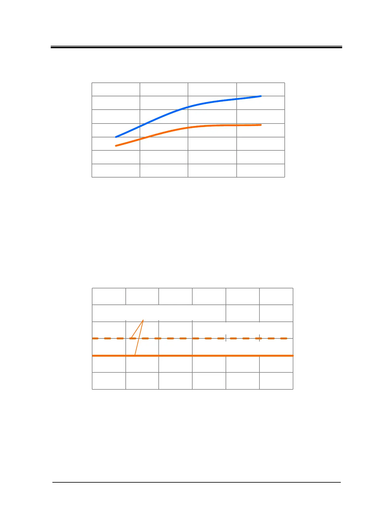
9.4.4 HRL100/200/300-A-40 CH2
Fig. 9-10 Cooling Capacity (HRL100/200/300-A-40 CH2)
0.0
0.5
1.0
1.5
2.0
2.5
3.0
10 15 20 25 30 35 40
Circulating fluid temperature [
o
C]
Ambienttemperature 45
o
C or less
(Max. 1.5 kW)
Rated 1.0 kW
0
5
10
15
20
25
30
35
0 10 20 30 40
Cooling capacity [kW]
Circulating fluid temperature [
o
C]
Ambienttemperature
32
o
C
45
o
C
Up to 1.5kW.However,when 1.5kW heat load is applied,
the cooling capacity of CH1 will decrease by 0.5kW.
This is the cooling capacity of the CH1 side when 1 Kw
heat load is applied to the CH2 side.

 Loading...


