EasyManua.ls Logo

SMC Networks HRSH150-A*-40 Series User Manual

Default Icon
200 pages
To Next Page IconTo Next Page
Page #1 background imageLoading...
Page #1 background image
HRX-OM-Q026
1
st
edition: December 2012
Rev. L: Nov.2017
Operation Manual
Installation Operation
Original Instructions
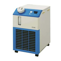
Thermo Chiller
HRSH Series
HRSH100-A
-20-
HRSH150-A
-20-
HRSH200-A
-20-
HRSH250-A
-20-

HRSH300-A
-20-
HRSH100-W
-20-
HRSH150-W
-20-
HRSH200-W
-20-
HRSH250-W
-20-
HRSH100-A
-40-
HRSH150-A
-40-
HRSH200-A
-40-
HRSH250-A
-40-

HRSH300-A
-40-
HRSH100-W
-40-
HRSH150-W
-40-
HRSH200-W
-40-
HRSH250-W
-40-
HRSH100-A
-20-
S
HRSH150-A
-20-
S
HRSH200-A
-20-
S
HRSH250-A
-20-
S

HRSH100-W
-20-
S
HRSH150-W
-20-
S
HRSH200-W
-20-
S
HRSH250-W
-20-
S
Keep this manual available whenever necessary
© 2017 SMC CORPORATION All Rights Reserved

Table of Contents

Question and Answer IconNeed help?

Do you have a question about the SMC Networks HRSH150-A*-40 Series and is the answer not in the manual?

SMC Networks HRSH150-A*-40 Series Specifications

General IconGeneral
BrandSMC Networks
ModelHRSH150-A*-40 Series
CategoryChiller
LanguageEnglish

Summary

Chapter 1 Safety Instructions

1.1 Before Using the Product

Essential safety precautions and manual understanding before product operation.

1.3 Hazards

Classifies hazards (Danger, Warning, Caution) and defines injury severity.

1.5 Safety Measures

Critical safety instructions for use and required personal protective equipment.

1.6 Emergency Measures

Procedures for immediate actions during emergencies like fire or earthquake.

Chapter 2 Name and Function of Parts

2.2 Name and Function of Parts

Identifies and describes major components for air-cooled and water-cooled units.

2.4 Operation Display Panel

Overview of the control panel, its buttons, indicators, and display functions.

Chapter 3 Transport and Setting Up

3.2 Installation

Guidelines for proper installation, including environmental conditions and space requirements.

3.3 Installation

Detailed procedures for product mounting, electrical wiring, and cable preparation.

Chapter 4 Starting the Product

4.1 Before Starting

Essential pre-operation checks covering installation, connections, and piping.

4.2 Preparation for Start

Steps for power supply connection, breaker setup, and initial settings.

4.3 Preparation of Circulating Fluid Supply to User’s Equipment

Instructions for supplying circulating fluid to connected user equipment.

4.4 Operation Start and Stop

Step-by-step guide for safely starting and stopping the thermo-chiller.

Chapter 5 Display and Setting of Various Functions

5.4 Alarm Menu

Information on how alarms are displayed, navigated, and reset.

5.11 Anti-freezing Function

Preventing circulating fluid from freezing by automatically operating the pump.

5.21 Alarm Customizing Function

Detailed settings for customizing alarm behavior, thresholds, and operations.

5.22 Communication Function

Configuration settings for serial communication and contact input/output.

Chapter 6 Alarm Notification and Troubleshooting

6.1 Alarm Notification

How the product signals and displays alarms, including operational responses.

6.3 Troubleshooting

Guidance on identifying causes and resolving issues based on alarm codes.

Chapter 8 Documents

8.6 Types of Hazard Labels

Explanation and location of warning labels indicating potential dangers.

Related product manuals