HRX-OM-X037
Chapter 3 Transport and Setting Up
3.3 Installation
HRL Series
Wiring of communication cable
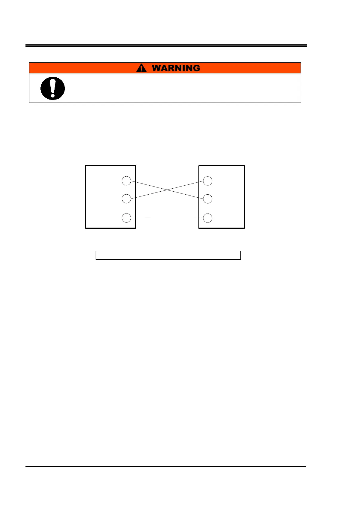
Be sure to wire as shown in the figure below.
Configuration
One thermo-chiller for one master.
Fig. 3-14 Connection of RS-232C
3.3.10 Ethernet Modbus/TCP Communication wiring
This product can operate the following by Ethernet Modbus/TCP
communication.
-Control of Run/Stop
-Circulating fluid temperature setting
-Circulating fluid temperature reading
-Operation status reading
-Alarm condition reading
Refer to Operation Manual Communication Function for more details.
2
3
5
RD
SD
SG
2
3
5
RD
SD
SG
Master This product
Be sure to turn OFF the breaker of the facility power supply (the
user's machine power supply) before wiring.
Do not connect any wire to other PIN numbers.

 Loading...


