HRX-OM-X037
Chapter 4 Starting the Product
HRL Series 4.2 Preparation for Start
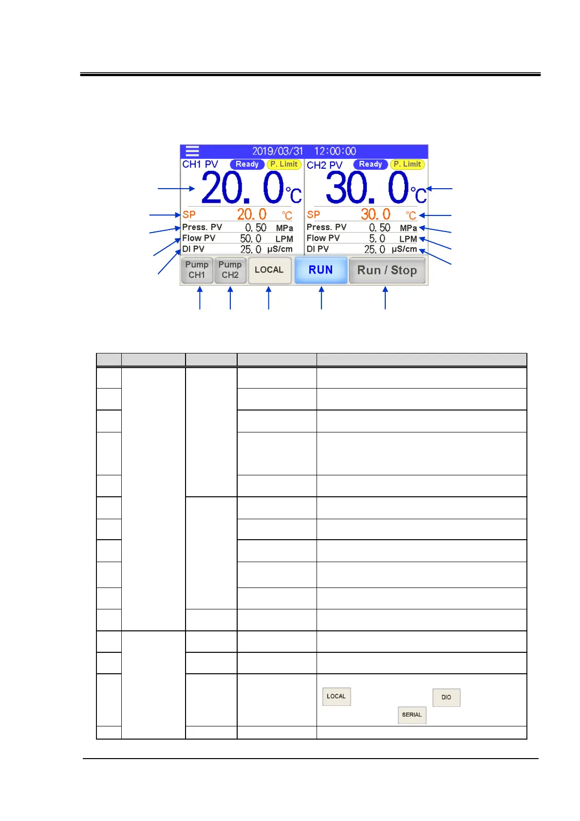
4.2.2 Operation screen (home screen)
Items displayed on the home screen are listed in Table 4.2-1 Items displayed
on the home screen.
Refer to Chapter 5 Display and Setting of Various Functions for details.
Fig. 4-4 Home screen
Table 4.2-1 Items displayed on the home screen
1 When option D1 “CH1 Electric conductivity control” is purchased, a numerical value is displayed.
No. Classification CH number Item Explanation
Circulating fluid
electric conductivity
It indicates the electric conductivity. 1
To select a operatrion mode from the touch panel
( mode), contact input ( mode) or
serial communication ( mode).
(15) Common
Run/Stop
To run/stop the product.
Circulating fluid
temperature
It indicates the current temperature.
Circulating fluid
set temperature
It indicates the set temperature.
Circulating fluid
Discharge pressure
It indicates the discharge pressure.
Circulating fluid
flow rate
It indicates the fluid flow rate. This value is
not measured by a flow meter. It should be
used as a reference value (rough indication).
It includes the flow rate in the bypass circuit.
Circulating fluid
temperature
It indicates the current temperature.
Circulating fluid
set temperature
It indicates the set temperature.
Circulating fluid
discharge pressure
It indicates the discharge pressure.
Circulating fluid
flow rate
t indicates the flow rate measured by a flow meter.
It does not include the flow rate in the bypass circuit.
Circulating fluid
electric conductivity
It indicates the electric conductivity.
Operating condition
display
It indicates the run and stop status of the
product.
CH1 pump operates independently w hile the button is
pressed.
Independent pump
operation
CH2 pump operates independently w hile the button is
pressed.
Independent pump
operation

 Loading...


