HRX-OM-X037
Chapter 5 Display and Setting of Various Functions
HRL Series 5.4 Description of the Screen
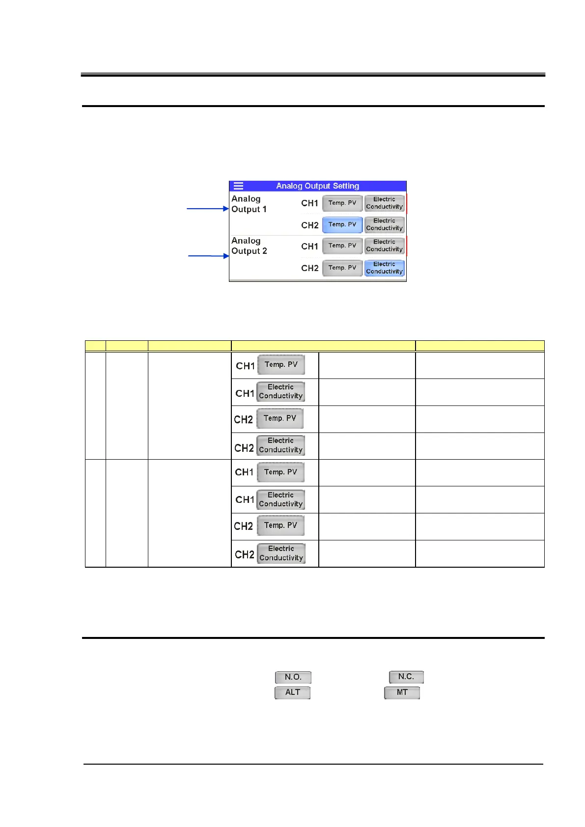
・Setting of analog output signal
3. The product has two analog outputs. The following signals can be output as analog signals:
・ Analog output signal 1–– “CH1 circulating fluid temperature” or “Electric conductivity
1”, “CH2 circulating fluid temperature” or “Electric conductivity”.
・ Analog output signal 2–– “CH1 circulating fluid temperature” or “Electric conductivity
1”, “CH2 circulating fluid temperature” or “Electric conductivity”.
1 In the case of option D1 "CH1 with electrical conductivity control", it can be set.
Table 5.4-26 Setting of analog output signal
1: By default.
2: In the case of option D1 "CH1 with electrical conductivity control".
・Setting of contact input signal form
4. The type and form of contact input signal are set. Following items can be set for contact input
signal 1 and 2:
・ Contact type…selects [ ] (A contact) or [ ] (B contact)
・ Signal form…・selects [ ] (alternate) or [ ] (momentary)
・ Signal type…・selects “OFF” (disabled), “External switch” (external switch signal) or
“Run/Stop” (run/stop) signal.
No. Indication Item Output
CH1 circulating fluid
temperature
2
CH1 electric conductivity
0.1–50.0 μ S/cm: 0.02–10.0 V
CH2 circulating fluid
temperature
CH2 electric conductivity
0.1–50.0 μ S/cm: 0.02–10.0 V
CH1 circulating fluid
temperature
2
CH1 electric conductivity
0.1–50.0 μ S/cm: 0.02–10.0 V
CH2 circulating fluid
temperature
*1
CH2 electric conductivity
0.1–50.0 μ S/cm: 0.02–10.0 V
Setting, selection and display
Setting of analog output signal

 Loading...


