HRX-OM-X037
Chapter 5 Display and Setting of Various Functions
5.4 Description of the Screen
HRL Series
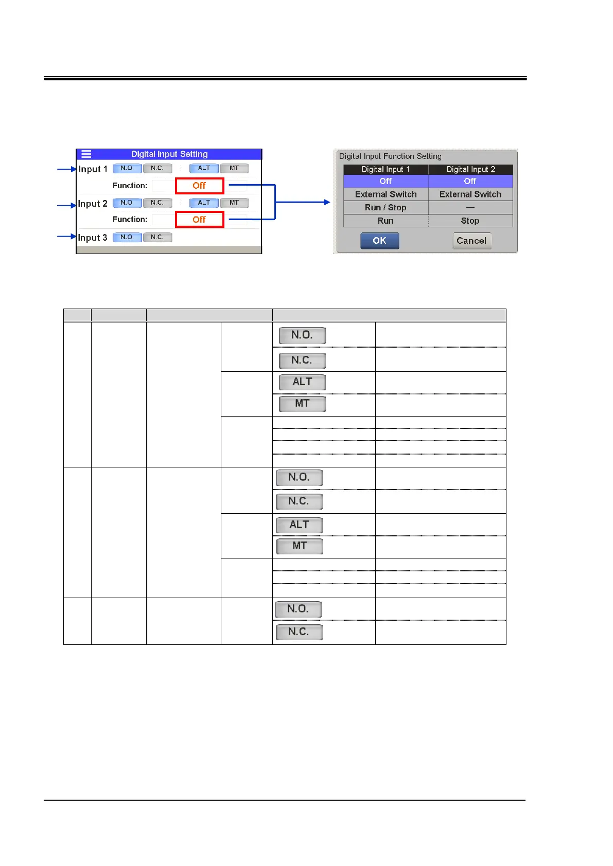
“Operation mode” can be switched from “Local mode/Serial mode” to “DIO mode” by inputting a
contact signal in contact input 3. Refer to the “Communication Function” of Operation Manual
for details.
Table 5.4-27 Setting of contact input signal form
A contact (normally open)
B contact
(normally closed)
A contact (normally open)
B contact
(normally closed)
Contact input
signal 3 3
A contact (normally open)
B contact
(normally closed)
1 : By default.
2 : This setting assigns “Run” signal to “Contact input 1” and “Stop” signal to “Contact input 2”.
3 : The signal form of contact input 3 is “Momentary”.
Setting of contact input signal form

 Loading...


