Do not modify the internal electrical wiring of the product. Incorrect
wiring may cause an electric shock or fire. Also, modifying the
internal wiring will void the product’s warranty.
NEVER connect the ground to water line, gas pipe or lightning
conductor.
The installation of electrical equipment and wiring work should be
performed only by personnel with sufficient knowledge and
experience.
Be sure to shut off the user’s power supply. Wiring with the product
energized is strictly prohibited.
The wiring must be conducted using cables complying with “Table
3.3-1” and firmly secured to the product to prevent the external force
of cables being applied to the terminals. Incomplete wiring, or
improper securing of wiring, may cause electrical shock or excessive
heat and fire.
Ensure a stable power supply with no voltage surges.
Ensure that an earth leakage breaker is used in the power supply of
the product. See “Table 3.3-1”.
Use a power supply suitable for the specifications of the product.
Use a power supply of over voltage category 3 (IEC60664-1)
*
.
Be sure to connect the ground connection.
Ensure that a lock out facility is available on the power supply.
Each product must have its own separate earth leakage breaker.
Otherwise, there can be a risk of electric shock or fire.
Ensure that no harmonics are superimposed at the power supply.
(Do not use inverters, etc.)
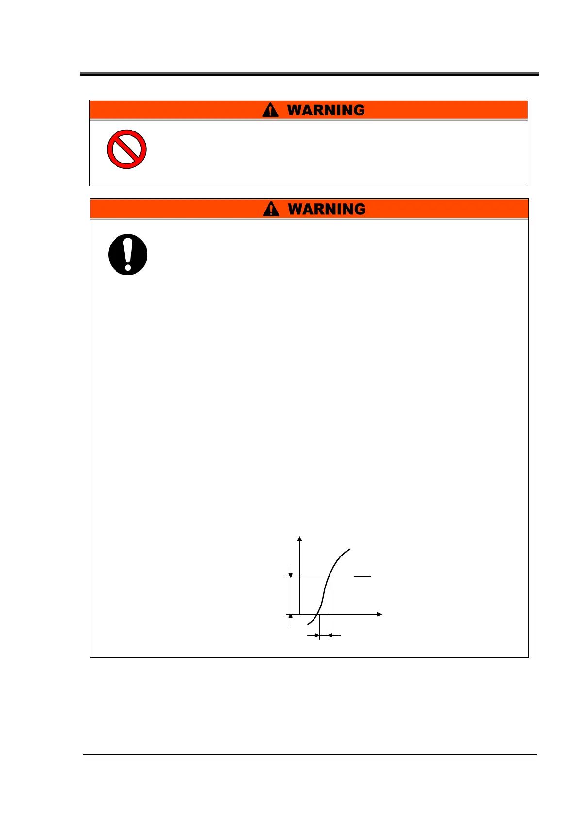
Supply a steady power supply which is not affected by surges or
distortion. In particular, if the voltage rate of increase (dv/dt) at zero
crossing exceeds 40V/200μsec, it may cause malfunction.

 Loading...


