EasyManua.ls Logo

SMC Networks HECR008-A5 User Manual

Default Icon
24 pages
To Next Page IconTo Next Page
Page #1 background imageLoading...
Page #1 background image
RoHS
(UL Standards)
Mountable in a 19-inch rack
Saves space by mounting multiple equipment
together in a rack.
±
0.01 °C to 0.03 °C
Temperature stability
10 °C to 60 °C
Set temperature range
Cooling capacity
Good space utilisation
Space saving design with reduced height
HECR008 (800 W)
HECR010 (1 kW)
176
mm
267
mm
Energy saving design
200 W
400 W
(HECR004/006)
1
(HECR008/010)
2
1: 200 W load 2: 500 W load
(HECR004/006)
1
(HECR008/010)
2
Low-noise design
55 dB
54 dB
HECR004 (400 W)
HECR006 (510 W)
HECR002 (200 W)
200
W
, 400
W
,
510
W
,
800
W
, 1
kW
Power consumption Noise level
New
New
New
New
New
New
Air-cooled
New
New
CAT.EUS40-61C-UK
Series HECR
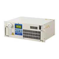
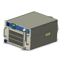
Peltier-Type Chiller
Thermo-con/
Rack Mount Type
Question and Answer IconNeed help?

Do you have a question about the SMC Networks HECR008-A5 and is the answer not in the manual?

SMC Networks HECR008-A5 Specifications

General IconGeneral
BrandSMC Networks
ModelHECR008-A5
CategoryChiller
LanguageEnglish

Summary

Peltier-Type Chiller HECR Series Overview

Core Functionality and Operation

Precise Temperature Control

Utilizes Peltier device for accurate fluid temperature management, refrigerant-free.

Construction and Operating Principles

Peltier Device Principle of Operation

Details the thermoelectric effect for precise heating and cooling control.

Model Selection Guide

Calculating Required Cooling Capacity

Methods to determine necessary cooling power with safety factors.

Advanced Model Selection and Precautions

Capacity Calculation Scenarios

Examples for unknown heat loads and time-based cooling requirements.

Product Specifications and Ordering

Comprehensive Technical Specifications

Detailed parameters for all HECR models, including electrical and fluid systems.

Cooling Capacity Performance Charts (HECR002-006)

Cooling Capacity Performance Charts (HECR008-010)

Heating Capacity Performance Charts (HECR002-006)

Heating Capacity Performance Charts (HECR008-010)

Pump Capacity Performance Charts (HECR002-006)

Pump Capacity Performance Charts (HECR008-010)

Dimensions and Connections (HECR002)

HECR002-A5 Physical Dimensions

Detailed layout and measurements of the HECR002-A5 unit.

HECR002 Connector Pinout

Configuration for power, communication, and sensor interfaces.

Dimensions and Connections (HECR004)

HECR004-A5 Physical Dimensions

Detailed layout and measurements of the HECR004-A5 unit.

HECR004 Connector Pinout

Configuration for power, communication, and sensor interfaces.

Dimensions and Connections (HECR006)

HECR006-A5 Physical Dimensions

Detailed layout and measurements of the HECR006-A5 unit.

HECR006 Connector Pinout

Configuration for power, communication, and sensor interfaces.

Dimensions and Connections (HECR008/010)

HECR008/010 Physical Dimensions

Detailed layout and measurements of the HECR008/010 units.

HECR008/010 Connector Pinout

Configuration for power, communication, and sensor interfaces.

Operation, Alarms, and Maintenance

Alarm Codes and Descriptions

Comprehensive list of error codes, their causes, and troubleshooting.

Safety and Product Precautions

Circulating Fluid Handling

Precautions for using and maintaining the circulating fluid.

Circulating Fluid Quality and Maintenance

Maintenance and Error Response

Procedures for upkeep and handling unit errors.

Related product manuals