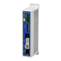
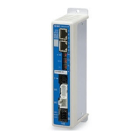
This document describes the JXC9H EtherNet/IP Direct Input High Performance Type Step Motor Controller (Servo/24 VDC) from SMC Corporation.
Function Description
The JXC9H controller is designed for precise control of step motors (servo 24VDC) in industrial automation applications, offering EtherNet/IP compatibility for seamless integration into network environments. It supports both positioning and pushing operations, allowing for versatile control of actuators based on either saved step data or numerical instructions.
Key functions include:
- EtherNet/IP Compatibility: Enables communication with EtherNet/IP networks for reading and writing information, facilitating remote control and monitoring.
- Actuator Control: Capable of controlling step motors for positioning operations and specific speed/force applications.
- Specified Force Operation: Allows control over gripping or pushing forces of the actuator.
- Separated Power Supply: Features separate power inputs for the motor and control circuits. This ensures that encoder position data is retained and EtherNet/IP/serial communication remains active even if motor power is turned off.
- Return to Origin: Supports returning the actuator to its origin position via an EtherNet/IP signal.
- Alarm Detection Function: Automatically detects abnormal conditions and outputs alarms via EtherNet/IP communication. Alarm history is stored in the controller's memory.
- Operation Modes: Offers both step data operation mode (using saved step data triggered by input/output port signals like DRIVE and INP) and numerical operation mode (executing operations by specifying numeric data for parameters like position, speed, acceleration, etc.).
- "AREA" Signal: Activates when the actuator's position falls within a predefined range (Area 1 and Area 2) set in the step data.
- Data Input Methods: Status monitoring, alarm resets, and step data/parameter setup can be performed via EtherNet/IP communication, ACT controller software, or a teaching box.
- Easy and Normal Modes: Provides two modes for controller setting software and teaching box. Easy mode simplifies setup for basic operations, while Normal mode allows for more detailed configuration.
- High Performance Type: Improved cycle time, increased maximum speed, and acceleration speed for enhanced performance.
Important Technical Specifications
Basic Specifications
- Compatible Motor: Step motor (servo 24 VDC).
- Power Supply Voltage: 24 VDC ±10%.
- Current Consumption: 200mA or less (Controller only). Total power consumption depends on the connected actuator.
- Compatible Encoder: Incremental A/B phase (800 pulse/rotation) and battery-less absolute encoder (4096 pulses/rotation).
- LED Display: Includes L/A1 (Link/Act 1), L/A2 (Link/Act 2), PWR (Power supply), ALM (Alarm status), MS (Controller status), and NS (Communication status) LEDs.
- Locking: Equipped with an unlocking terminal.
- Actuator Cable Length: 20 m or less.
- Cooling Method: Air-cooling type.
- Operating Temperature Range: 0°C to 40°C (No freezing).
- Operating Humidity Range: 90% RH or less (No condensation).
- Insulation Resistance: 50 MΩ (500 VDC) between external terminals and case.
- Weight: 250 g (Screw mounting type), 270 g (DIN rail mounting type).
EtherNet/IP Communication
- Protocol: EtherNet/IP™ (Conformance test version CT-17).
- Communication Speed: 10/100 Mbps (automatic negotiation).
- Communication Cable: Standard Ethernet cable (STP, CAT5 or higher, 100BASE-TX).
- Communication Method: Full duplex/Half duplex (automatic negotiation).
- Setup File: EDS file (downloadable from SMC website).
- Occupied Area: Input 36 byte/Output 36 byte.
- IP Address Setting Range: 192.168.1.1 to 254 (set by rotary switch) or arbitrary address via DHCP server.
- Vendor ID: 7h (SMC Corporation).
- Product Type: 2Bh (Generic Device).
- Product Code: 0100h.
Usage Features
Startup Procedure
- Package Contents Check: Verify all accessories are present.
- Mounting: Mount the controller using either screw mounting (JXC9H7-□) or DIN rail mounting (JXC9H8-□). Ensure proper grounding.
- Controller Setting: Set the IP address using the rotary switches (X1, X10, X100) on the controller.
- PLC Setup: Configure the PLC as a master station.
- Wiring and Connection: Connect cables to the controller, including power (PWR), motor (MOT), encoder (ENC), serial I/O (SI), and EtherNet/IP (P1, P2) connectors.
- Power Supply: Supply 24VDC power. Monitor PWR and ALM LEDs for normal operation.
- Setting Parameters: Configure controller parameters using setting software or teaching box. Monitor MS and NS LEDs for proper communication.
- Operation Parameters Setup: Define operation patterns (step data, basic parameters, return to origin parameters) via PC software or teaching box.
- Test Run: Input signals from the PLC to check operation, referring to the memory map and operation instructions.
Wiring and Connections
- Power Supply Plug (CN1): Connects to 24VDC power. Includes terminals for control power (C24V), motor power (M24V), stop signal (EMG), lock release (LK RLS), and common power (0V).
- Motor Connector (MOT) & Encoder Connector (ENC): Connect to the actuator via the actuator cable.
- Serial I/O Connector (SI): Used for connecting a teaching box (via conversion cable) or a PC (via communication cable and USB conversion unit).
- Communication Modular (P1, P2): Connects to the EtherNet/IP network using a standard Ethernet cable.
Operation Methods
- Operation by Step No.: Actuator operations are driven by sending specific commands over the network, based on preset step data.
- Operation by Numerical Instruction: Actuator speed, position, acceleration, deceleration, pushing force, etc., can be specified by numerical values, provided they are within allowable ranges.
LED Display
LEDs on the controller provide status indications for power (PWR), alarms (ALM), controller status (MS), and EtherNet/IP communication status (NS, L/A1, L/A2). Different LED states (ON, OFF, flashing, red, green) indicate various operational conditions or errors.
Interrupting Operations
Three methods for interrupting operation are available:
- "EMG" Signal: Decelerates and stops the actuator, turning off the servo. The stopped position is not held (unless the actuator has a lock).
- "RESET" Signal: Decelerates and stops the actuator, holding the stopped position (servo remains ON).
- "HOLD" Signal: Decelerates the actuator to a stop, holding the stopped position (servo remains ON).
Maintenance Features
Safety Instructions
- Always turn off the power supply before adjusting, mounting, or wiring.
- Do not disassemble the cable or connect/disconnect cables with power on.
- Ensure secure wiring and proper grounding to prevent electric shock, malfunction, or damage.
- Avoid routing wires with power or high voltage cables to prevent interference.
- Do not touch the motor during operation (can reach 90-100°C).
- Immediately shut off power if abnormal heating, smoke, or fire occurs.
- Stop operation if abnormal noise or vibration occurs.
- Never touch rotating or moving parts of the actuator during operation.
- When installing, adjusting, inspecting, or maintaining, shut off power and implement safety measures.
- For actuators with servo motors, be aware of the "motor phase detection step" which involves slight movement upon SVON activation.
Maintenance Precautions
- Disassembly/Repair: Do not disassemble or repair the product.
- Voltage Check: Always check for residual voltage with a tester 5 minutes after power-OFF before modifying or checking wiring.
- Manual Actuator Movement: Disconnect the electric actuator cable before manually moving the slider to prevent damage from induced voltage.
- Lubrication: The product is lubricated for life and does not require service lubrication. Contact SMC if lubrication is needed.
- Periodic Checks: Perform maintenance checks periodically, confirming wiring and screws are not loose.
- Functional Inspection: Conduct appropriate functional inspection and test after completing maintenance.
- Prohibited Actions: Do not put anything conductive or flammable inside the controller. Do not perform insulation resistance or withstand voltage tests.
- Space: Ensure sufficient space for maintenance and inspection activities.
Troubleshooting
The manual provides a detailed troubleshooting guide based on LED status and communication issues, directing users to specific sections for countermeasures. Common issues include:
- LED is OFF: Check power supply and wiring.
- MS or NS LED is ON but not solid green/flashing: Indicates configuration errors, PLC stop, communication idling, or IP address issues.
- ALM LED turns ON red: Indicates an alarm, requiring reference to the alarm for motor control section.
- Communication fault: Check USB driver installation, COM port settings, and cable connections.
- Actuator does not operate: Check specifications, power supply, and EMG terminal voltage.
- Operation stops intermittently: Check wiring, parameters, voltage drop, and signal timing.
- Actuator does not move to correct position: Check origin position, parameters, and wiring.
- Speed not achieved: Check operation pattern, parameters, and voltage drop.
Handling of Sent/Received Data
The manual explains how to handle 1-byte, 2-word, and negative value data, particularly for alarm codes and target position values, including hexadecimal representations and two's complement notation for negative values.