- 48 -
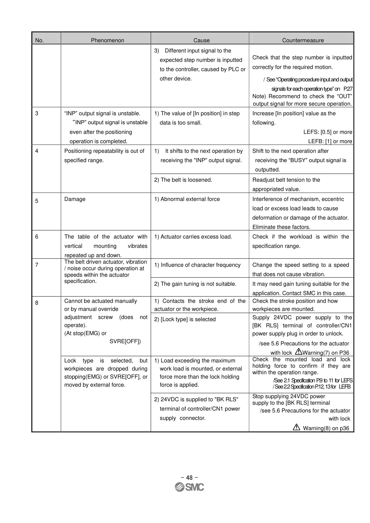
3) Different input signal to the
expected step number is inputted
to the controller, caused by PLC or
other device.
Check that the step number is inputted
correctly for the required motion.
/ See “Operating procedure input and output
signals for each operation type” on P.27
Note) Recommend to check the “OUT”
output signal for more secure operation.
“INP” output signal is unstable.
“INP” output signal is unstable
even after the positioning
operation is completed.
1) The value of [In position] in step
data is too small.
Increase [In position] value as the
following.
LEFS: [0.5] or more
LEFB: [1] or more
Positioning repeatability is out of
specified range.
1) It shifts to the next operation by
receiving the "INP" output signal.
Shift to the next operation after
receiving the “BUSY” output signal is
outputted.
Readjust belt tension to the
appropriated value.
1) Abnormal external force
Interference of mechanism, eccentric
load or excess load leads to cause
deformation or damage of the actuator.
Eliminate these factors.
The table of the actuator with
vertical mounting vibrates
repeated up and down.
1) Actuator carries excess load.
Check if the workload is within the
specification range.
The belt driven actuator, vibration
/ noise occur during operation at
speeds within the actuator
specification.
1) Influence of character frequency
Change the speed setting to a speed
that does not cause vibration.
2) The gain tuning is not suitable.
It may need gain tuning suitable for the
application. Contact SMC in this case.
Cannot be actuated manually
or by manual override
adjustment screw (does not
operate).
(At stop(EMG) or
SVRE[OFF])
1) Contacts the stroke end of the
actuator or the workpiece.
Check the stroke position and how
workpieces are mounted.
2) [Lock type] is selected
Supply 24VDC power supply to the
[BK RLS] terminal of controller/CN1
power supply plug in order to unlock.
/see 5.6 Precautions for the actuator
with lock Warning(7) on P36
Lock type is selected, but
workpieces are dropped during
stopping(EMG) or SVRE[OFF], or
moved by external force.
1) Load exceeding the maximum
work load is mounted, or external
force more than the lock holding
force is applied.
Check the mounted load and lock
holding force to confirm if they are
within the operation range.
/See 2.1 Specification P.9 to 11 for LEFS
/ See 2.2 Specification P.12, 13 for LEFB
2) 24VDC is supplied to "BK RLS"
terminal of controller/CN1 power
supply connector.
Stop supplying 24VDC power
supply to the [BK RLS] terminal
/see 5.6 Precautions for the actuator
with lock
Warning(8) on p36
2021-05-2010:32
DW913599
 Loading...