Z_ISE10-TF2Z051EN
Page 1 of 3
Instruction Manual
High Precision Digital Pressure Switch
Series ZSE10(F) / ISE10
The intended use of this digital pressure switch is to measure, monitor
and display pressure and to provide an output signal.
1 Safety Instructions
These safety instructions are intended to prevent hazardous situations
and/or equipment damage. These instructions indicate the level of
potential hazard with the labels of “Caution,” “Warning” or “Danger.”
They are all important notes for safety and must be followed in addition
to International Standards (ISO/IEC)
*1)
, and other safety regulations.
*1)
ISO 4414: Pneumatic fluid power - General rules relating to systems.
ISO 4413: Hydraulic fluid power - General rules relating to systems.
IEC 60204-1: Safety of machinery - Electrical equipment of machines.
(Part 1: General requirements)
ISO 10218-1: Robots and robotic devices - Safety requirements for
industrial robots - Part 1: Robots.
• Refer to product catalogue, Operation Manual and Handling
Precautions for SMC Products for additional information.
• Keep this manual in a safe place for future reference.
Caution indicates a hazard with a low level of risk which, if
not avoided, could result in minor or moderate injury.
Warning indicates a hazard with a medium level of risk
which, if not avoided, could result in death or serious injury.
Danger indicates a hazard with a high level of risk which, if
not avoided, will result in death or serious injury.
Warning
• Always ensure compliance with relevant safety laws and
standards.
• All work must be carried out in a safe manner by a qualified person in
compliance with applicable national regulations.
• This product is class A equipment intended for use in an industrial
environment. There may be potential difficulties in ensuring
electromagnetic compatibility in other environments due to conducted
or radiated disturbances.
Otherwise electric shock, malfunction or product damage can result.
• Refer to the operation manual on the SMC website (URL:
https://www.smcworld.com) for more safety instructions
.
2 Specifications
2.1 General specifications
∗ If the applied pressure fluctuates around the set value, the hysteresis must be
set to a value more than the amount of fluctuation or chattering will occur.
2.2 Piping / Weight specifications
Model No. M5 M5R 01 N01
Port size M5 x 0.8 M5 x 0.8
Silicon
Piping port C3602 (electroless nickel plating), O-ring: HNBR
15 g 23 g
wire and
55 g 63 g
Warning
Special products (-X) might have specifications different from those
shown in this section. Contact SMC for specific drawings.
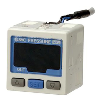
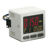
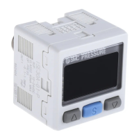
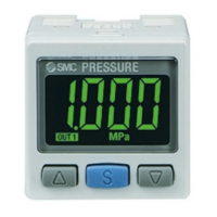
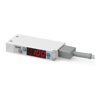
3 Name and function of product parts
Output (OUT1) LED (Green): LED is ON when the switch output (OUT1)
is ON.
Output (OUT2) LED (Red): LED is ON when the switch output (OUT2)
is ON.
LED display: Displays the current status of pressure, setting
mode and error code.
button (UP): Selects the mode or increases the ON/OFF set
value.
Press this button to change to peak display mode.
button (DOWN): Selects the mode or decreases the ON/OFF set
value.
Press this button to change to bottom display
mode.
button (SET): Press this button to change to another mode and
to set a value.
4 Installation
4.1 Installation
Warning
Do not install the product unless the safety instructions have been read
and understood.
4.2 Direct Mounting
• Mount using the M3 set screws (2 pcs.) supplied for direct mounting.
Required tightening torque is 0.5 to 0.7 N•m.
4 Installation (continued)
4.3 Mounting with panel mount adapter
• Panel mount adapter (Part No.: ZS-39-B)
• Front protective cover (Part No.: ZS-39-01)
• Panel mount adapter + Front protective cover (Part No.: ZS-39-D)
4.4 Mounting with DIN rail adapter
• Prepare a DIN rail adapter for mounting on the DIN rail (Part No.: ZS-
39-R).
• Take care not to bend the claws of the DIN rail adapter when mounting.
Mounting on to the DIN rail
Engage the Pressure switch with claw 2 of the DIN rail adapter, then
press down on to claw 1 until it clicks.
Engage claw 1 of the adapter on to the DIN rail as shown [1], apply force
in direction [2], then press downward [3] until claw 2 clicks on to the DIN
rail.
Removal from DIN rail
Move in the direction [1], then remove claw 1 in direction [2] as shown.
Model No.
Air, inert gases, non-combustible gases
Rated pressure range
Set pressure range
Power supply voltage 12 to 24 VDC (±10%), ripple 10% (p-p) max.
Current consumption 40 mA or less
Protection Polarity protection
NPN or PNP open collector: 2 outputs
80 mA
28 V (for NPN output)
2 V or less (at 80 mA load current)
Response time
2.5 ms or less (anti-chatter function: 20, 100,
500, 1000, 2000 ms)
Hysteresis
Hysteresis mode
0 to variable
1 to 5 V ±2.5% F.S.
3 1/2 digits, 7-segment display, colour (red)
Display accuracy
±2% F.S. ±1 digit
(at ambient temperature 25±3
o
Indicator light
LED is ON when output is ON
(OUT1: Green, OUT2: Red)
0, 10, 50, 100, 500, 1000, 5000 ms
Ambient temperature
range
Operation: -5 to 50
o
C, Storage: -10 to 60
o
C
(no condensation or freezing)
Operation, Storage: 35 to 85%RH
(no condensation)
Withstand voltage
1000 VAC for 1 minute
between terminals and housing
Insulation resistance
50 MΩ or more at 500 VDC
between terminals and housing
Temperature
characteristics
±2% F.S. (25
o
C reference)
Lead wire
Oil resistant vinyl cabtyre cable
5 cores φ3.5 mm, 2 m long
Sectional area of conductor: 0.15 mm
2
(AWG26)
Outside diameter of insulator: 1.0 mm