Z_ISE10-TF2Z051EN
Page 2 of 3
4 Installation (continued)
4.5 Environment
Warning
• Do not use in an environment where corrosive gases, chemicals, salt
water or steam are present.
• Do not use in an explosive atmosphere.
• Do not expose to direct sunlight. Use a suitable protective cover.
• Do not install in a location subject to vibration or impact. Check the
product specifications.
• Do not mount in a location exposed to radiant heat.
• Do not use in a place where electrostatic charge will be a problem.
4.6 Piping
Caution
• Before piping make sure to clean up chips, cutting oil, dust etc.
• When installing piping or fittings, ensure sealant material does not
enter inside the port. When using seal tape, leave 1 thread exposed
on the end of the pipe/fitting.
• Tighten fittings to the specified tightening torque.
4.6.1 Tightening torque for piping
The required tightening torque of the piping port is 1 N•m for M5 thread.
(equivalent to approximately 1/6 extra tightening after manual tightening)
and 7 to 9 N•m for R1/8 and NPT1/8 threads.
4.6.2 Connection using One-touch fitting
1. Cut the tube end perpendicular.
2. Hold the tube and insert it into the One-touch fitting slowly until it
bottoms out.
• Allow sufficient tube length to prevent twist and tensile or moment
loads from being applied to the fitting or tube.
• When using a tube manufactured by a company other than SMC,
check that its outside diameter tolerance satisfies the following values:
1) Nylon tube: ±0.1 mm maximum
2) Soft nylon tube: ±0.1 mm maximum
3) Polyurethane tube: +0.15 mm / -2 mm maximum
4.7 Lubrication
Caution
• SMC products have been lubricated for life at manufacture, and do not
require lubrication in service.
• If a lubricant is used in the system, use turbine oil Class 1 (no additive),
ISO VG32. Once lubricant is used in the system, lubrication must be
continued because the original lubricant applied during manufacturing
will be washed away.
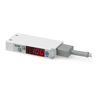
5 Wiring
5.1 Wiring connections
• Connections should be made with the power supply turned off.
• Use a separate route for the product wiring and any power or high
voltage wiring. Otherwise, malfunction may result due to noise.
• Ensure that the FG terminal is connected to ground when using a
commercially available switch-mode power supply. When a switch-
mode power supply is connected to the product, switching noise will
be superimposed and the product specification can no longer be met.
This can be prevented by inserting a noise filter, such as a line noise
filter and ferrite core, between the switch-mode power supply and the
product, or by using a series power supply instead of a switch-mode
power supply.
5 Wiring (continued)
5.2 Connector attaching / detaching
• When mounting the connector, insert it straight into the socket, holding
the lever and connector body, and push the connector until the lever
hooks into the housing, and locks.
• When removing the connector, press down the lever to release the
hook from the housing and pull the connector straight out.
Connector pin numbers
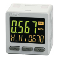
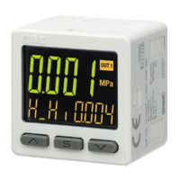
6 Pressure Setting
6.1 Measurement mode
Measurement mode is the condition where the pressure is detected and
displayed, and the switch function is operating.
This is the basic mode, and other modes should be selected for setting
changes and function settings.
6.2 Setting the ON and OFF points of the Pressure switch
When the pressure exceeds the set value, the Pressure switch will turn
ON.
When the pressure falls below the set value by the amount of hysteresis
or more, the Pressure switch will turn OFF.
The default setting of the output set value is the central value between
the atmospheric pressure and the upper limit of the rated pressure range.
6 Pressure Setting (continued)
If this condition, shown below, is acceptable, then keep these settings.
<Operation>
[Hysteresis mode]
1. Press the SET button once in measurement mode.
2. [P_1] or [n_1] and the set value are displayed in turn.
3. Press the UP or DOWN button to change the set value.
The UP button is to increase and the DOWN button is to decrease.
• Press the UP button once to increase by one digit and press it
continuously to keep increasing the set value.
• Press the DOWN button once to decrease by one digit and press it
continuously to keep decreasing the set value.
4. Press the SET button to finish the setting.
For models with 2 outputs, [P_2] or [n_2] will be displayed. Set as
above.
The Pressure switch operates within a set pressure range (from P1L to
P1H) during window comparator mode. Set P1L (switch lower limit) and
P1H (switch upper limit) using the setting procedure above.
When reversed output is selected, [n1L] and [n1H] are displayed.
6.3 Zero clear of Display
The display is reset to zero when the UP and DOWN buttons are pressed
simultaneously for 1 second. For the first operation, always perform zero
clear with no pressure applied.
7 Function Setting
In measurement mode, press the SET button for 2 seconds or longer to
display [F 0]. Select to display the function to be changed [F ].
Press the SET button for 2 seconds or longer to return to measurement
mode.
Note: Some functions are not available depending on part number. All functions are
displayed with [F ] followed by the function description. If a function is not available,
the function is displayed as [---].
7.1 Default Function settings
At the time of shipment, the following settings are provided.
If this condition is acceptable, then keep these settings.
To change the settings, enter function selection mode.
Units specification Pressure range Default setting
"Nil" or M
MPa
kPa
P
psi
• F 1] Setting of OUT1
Item Description Default setting
Output mode
window comparator mode or
Hysteresis mode
Select reversed output.
Normal output
Pressure
setting
Set the ON or OFF point of the
switch output
ZSE10: -50.5 kPa
Hysteresis
Set the hysteresis to prevent
chattering.
ZSE10: 5.1 kPa
• [F 2] Setting of OUT2 is the same setting as [F 1] OUT1.
• Other parameter settings
[F 4] Auto-preset function
[F 6] Fine adjustment of display value
[F90] Setting of all functions
[F99] Reset to the default setting
8 Other Settings
• Peak/bottom value indication
• Zero clear function
• Key-lock function
For further details refer to the operation manual on the SMC website
(URL: https://www.smcworld.com
).
 Loading...