Panel mount
adapter
Panel mount
adapter
Panel
Claw
Mounting screw
M3 x 5L
Bracket B
Lever
Lead wire (Brown)
Lead wire (Blue)
Mounting screw
M3 x 5L
Bracket A
Tube
One-touch fitting
1.
Do not drop, bump, or apply excessive impacts (100
m/s
2
) while handling. Although the body of the pres-
sure switch may not be damaged, the internal parts
of the pressure switch could be damaged and lead
to a malfunction.
2. The tensile strength of the cord is 35 N. Applying
a greater pulling force on it can cause a malfunc
-
tion. When handling, hold the body of the sen
-
sor—do not dangle it from the cord.
3.
Do not exceed the screw-in torque of 7 to 9 N·m
when installing piping. Exceeding these values
may cause malfunctioning of the switch.
4. Do not use pressure switch with corrosive and/or
flammable gases or liquids.
5. Allow a sufficient margin of tube length in piping
in order to prevent application of torsional, tensile
or moment load to the tubes and fittings.
6. When a brand of tubing other than SMC is used,
make sure that the tolerance of the tube's O.D. sa
-
tisfies following specifications:.
1) Nylon tubing: ±0.1 mm or less
2) Soft nylon tubing:
±0.1 mm or less
3) Polyurethane tubing: +0.15 mm or less, –0.2 mm or less
7. The applicable fluid is air. Consult SMC if the
Warning
Handling
1. Incorrect wiring can damage the switch and cause
a malfunction or erroneous switch output. Con
-
nections should be done while the power is tur
-
ned off.
2. Do not attempt to insert or pull the connector
when the power is on. A switch output malfunc
-
tion may occur.
3. Wire separately from power lines and high voltage
lines, avoiding wiring in the same conduit with
them. Malfunctions may occur due to noise from
these other lines.
4. If a commercial switching regulator is used, make
sure that the F.G. terminal is grounded.
Connection
Warning
1.
SMC pressure switches are CE marked; however,
they are not equipped with surge protection against
lightning. Lightning surge countermeasures should
be applied directly to system components as neces-
sary.
2.
SMC pressure switches do not have an explosion
proof rating. Never use in the presence of an explo-
sive gas as this may cause a serious explosion.
3. Do not use in an environment where static electri-
city can cause problems, otherwise system failure
Operating Environment
Warning
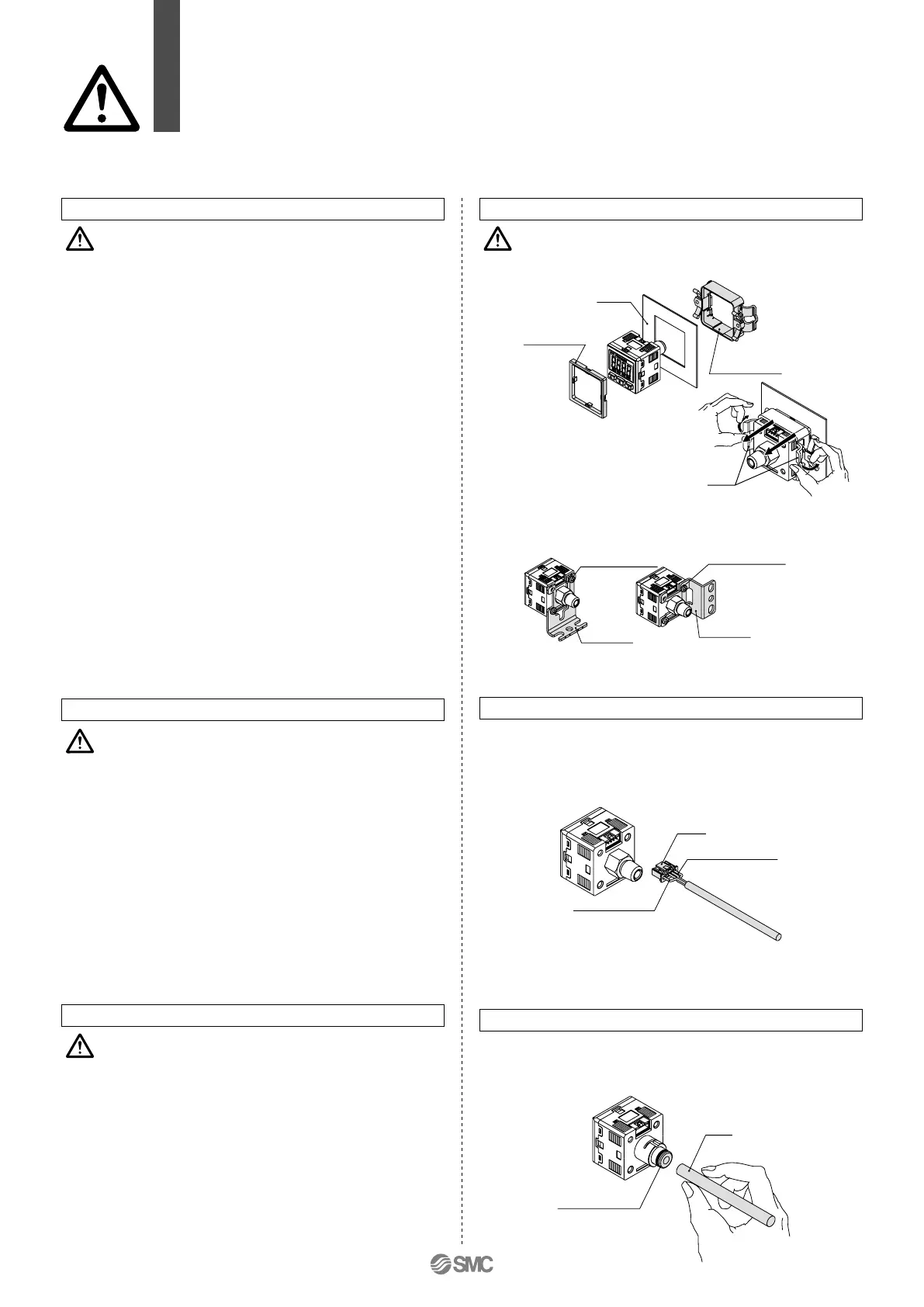
1. Mounting/removing with panel mount adapter
2. Mounting with bracket.
• Mount a bracket to the using two M3 x 5L mounting screws and
install on piping. The switch can be installed horizontally depen-
ding on the installation location.
To release push the clips out
-
ward as shown on the picture,
and pull back towards you.
Caution
Mounting
• To connect the connector, insert it straight while pinching the
lever, and then push the lever into the jack of the housing and
lock it.
•
To remove the connector, pull it straight out while applying pres-
sure with your thumb to the lever and unhooking it from the jack.
• When using bracket B, take piping dimensions into considera-
tion for installation.
• Do not attempt to insert or pull the pressure sensor or its con
-
nector when the power is on. A switch output malfunction may
occur.
Connection/Removal of Connector
• Cut the tube perpendicularly.
• Hold the tube and insert it into the one-touch fitting carefully
and securely all the way to the bottom.
Piping
Tightening torque
for bracket moun-
ting screw should
be 0.5 to 0.7
N·m.
Series ZSE30A
(
F
)
/ISE30A
Specific Product Precautions 1
Be sure to read this before handling.
Refer to the back of pages 1 and 2 for Safety Instructions and “Precautions for
Handling Pneumatic Devices” (M-03-E3A) for Pressure Switches Precautions.
Set the pressure within the rated pressure range.
The set pressure range is the range of pressure that is possible to be set.
The rated pressure range is the range of pressure that satisfies the specifications (accuracy, linearity, etc.) on the switch.
Although it is possible to set a value outside the rated pressure range, the specifications will not be guaranteed (even if the value stays
within the set pressure range).
Caution
Set Pressure Range and Rated Pressure Range
Rated pressure range of switch
Set pressure range of switch
Switch
–100 kPa 0 100 kPa 500 kPa 1 MPa
Pressure range
ZSE30AF
ISE30A
–100 kPa
–105 kPa
100 kPa
105 kPa
For
com
-
pound
pressure
For
positive
pressure
For
vacuum
pressure
ZSE30A
–101 kPa
–105 kPa
0
10 kPa
1 MPa
–105 kPa
(–0.105 MPa)
1.05 MPa
–100 kPa
Series ZSE30A
(
F
)
/ISE30A
Specific Product Precautions 2
Be sure to read before handling.
Refer to the back of pages 1 and 2 for Safety Instructions and “Precautions for
Handling Pneumatic Devices” (M-03-E3A) for Pressure Switches Precautions.
 Loading...