3mm A/F ball-ended wrench which should be inserted into each lock in turn. When
released the sub-chassis will rise under the pull of the suspension bands so have an
assistant hold it firmly down until all the locks have been operated as damage could occur
if one end lifts before the other.
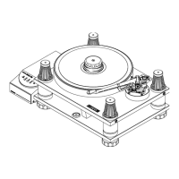
9. SETTING UP
1. The motor is mounted on three height adjustment screws, the points of which nest in
compliant cups in the base. For transit purposes these screws have been backed off clear
of the compliant cups and the motor secured to the base with the Motor Transit Screw.
This must be removed using the long leg of the 2.5A/F hexagon wrench as a lever through
the cross hole in the head of the screw. The ends of the height setting gauge (1084) are
marked A and B. Re-engage the points of the height adjustment screws with the compliant
cups and adjust so that end B of the gauge is just admitted near each screw in turn
between the underside of the motor and the surface of the base.
2. For transit the main bearing is off-loaded by the four pulley transit screws. These are
captive and should be turned anti-clockwise with the 3mm A/F hexagon wrench until they
stop. Ensure the wrench is fully engaged to avoid damage to the transit screw socket.
3. Unpack the drive belt and place it over the driven pulley. Press it down as far as the
flange, ensuring that it is free from twists, then stretch it over the motor pulley. The
pulleys will be out of alignment without the weight of the platter so rotation must not take
place until it has been fitted.
4. Remove and unpack the platter from the bottom section of the case . Place it carefully and
squarely over the turntable spindle and lower it gently down until it rests on the driven
pulley, having first ensured that both mating surfaces are clean. Rotate the platter slowly
by hand to position the belt on the pulleys.
5. The base should now be levelled by rotating the supporting feet until the bubble and
reference ring of the spirit level are concentric. The feet will turn more readily if the
corresponding corner of the base is lifted slightly at the same time.
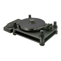
6. The Model 30/2 is intended to receive an SME Series V precision pick-up arm and is
supplied complete with a non-standard 1.8M (6 ft) audio lead, the plug contacts of which
have been rotated through ninety degrees so the cable can leave the arm downwards.
7. If you are not already familiar with the Series V arm, carefully study its instruction book
at this point. Fit the cartridge of your choice and feed the audio lead up through the cut-
out in the arm mounting plinth. Do not over-tighten the four M5 x 30 socket cap screws
holding the arm mounting plinth to the sub-chassis. The intended interface will be
obtained if the screws are tightened holding the short leg of the hexagon wrench. Plug the
lead into the arm, which should now be secured to the arm mounting plinth using the four
M3 x 12mm socket cap screws provided. Two cable grips are fitted to the underside of the
sub-chassis. Select whichever is the more convenient and remove the clamp by squeezing
in the two release pads. Position the audio lead and re-fit the clamp, pushing it home just
enough to secure the cable in a shallow loop so that it is held clear of the base.
8. The arm mounting plinth is fitted with jacking screws to facilitate removal from the sub-
chassis. They should be turned clockwise, alternately in small increments until the plinth
can be lifted off. A 2.0mm A/F hexagon wrench Part No. 5924 is provided for this
purpose.
10
 Loading...