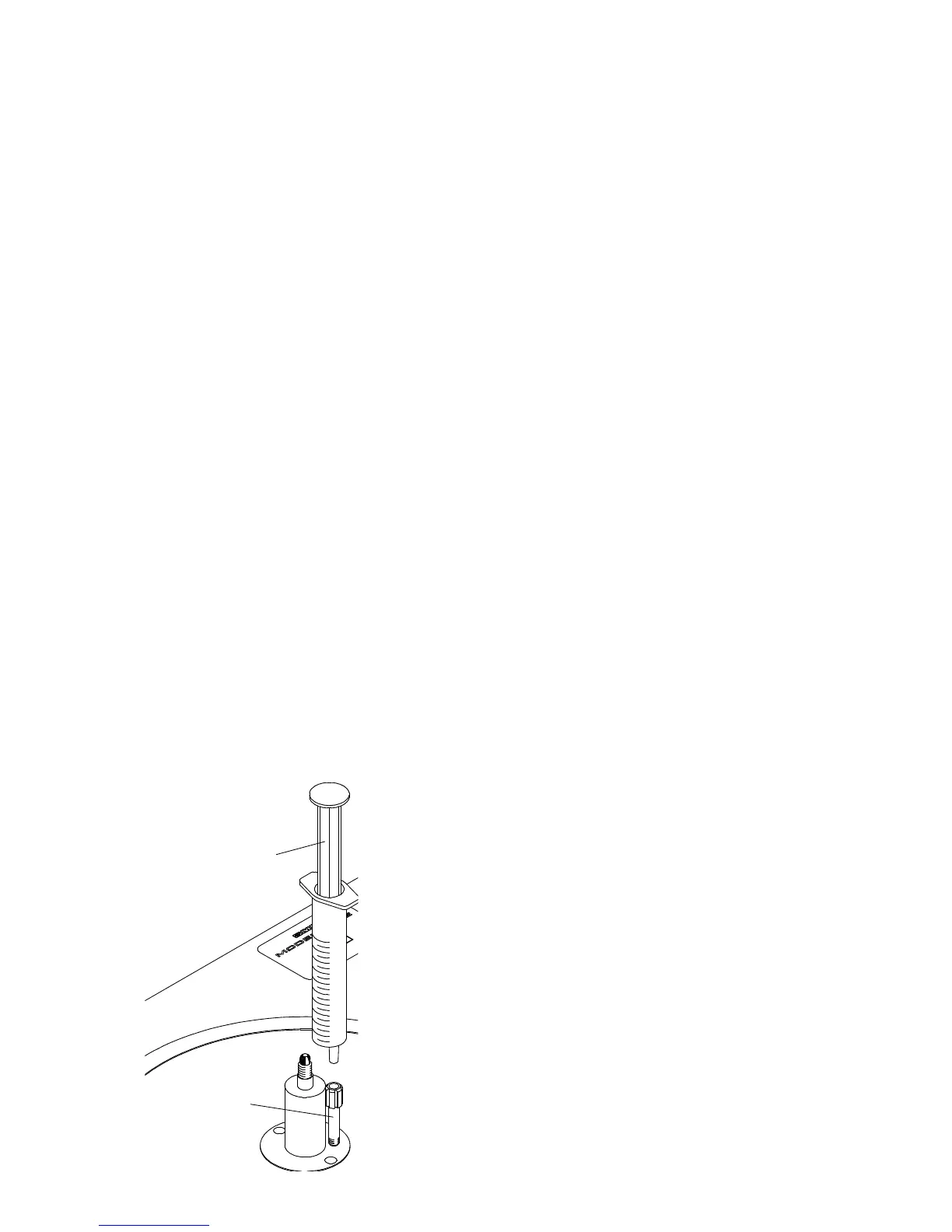
Syringe of
Spindle Oil
8. UNPACKING
1. Unpack and check all items against the packing list on Page 7. Any missing parts should
be reported to your dealer at once.
2. The levelling feet allow for two methods of interface with the mounting surface.
a. As received on rubber insert pads set into the underside of the feet.`
b. Stainless steel balls also set into the underside of the feet.
WARNING:
Method (b) is not suitable for delicate surfaces as indentation may be caused.
3. If hard mounting the turntable on the stainless steel balls is preferred, proceed as follows:
a. Position the base so that one end overhangs the table by about 10cms, unscrew
and remove both of the exposed feet.
b. Remove the rubber pad from the foot by pushing out through the small hole on
the upper side of the foot using the longer leg of the 2mm A/F hexagon
wrench.
c. Replace the turntable feet and repeat the procedure for the two feet at the
opposite end of the unit.
4. Having removed the lid of the packing case take out the tray containing the tools and
accessories. Due to the weight of the Model 30/2 it is best lifted out of the case by two
people, one at each end holding it under the sub-chassis. The turntable should be sited on
a substantial table or steel equipment stand which must be capable of firmly supporting at
least 45 kilos (100 lbs).
5. Position the base so that its left-hand end overhangs the table by about 10 cms (4”). This
allows access to the transit screw which secures the motor and is beneath it. Remove this
screw then restore the base to its normal position.
6. The turntable is packed with only a little oil in the bearing housing and this should now be
filled. A metered charge is provided in Syringe Part No:
1058/30.
7. Remove the syringe from its packing and insert the tip
into the Oil Filler Adaptor, which will be found already
fitted to near the spindle. (as illustration left).
8. Slowly inject the complete quantity into the bearing
maintaining downward pressure throughout the operation to
prevent leakage.
9. Remove the syringe and dispose of it responsibly!
10. Unscrew and remove the Oil Filler Adaptor using the
Box Spanner Part No: 1946. Retain the adaptor for possible
future use.
11. For transit the suspension is secured by four locks, two
at either end of the sub-chassis close to the columns.
Locking or unlocking requires five complete turns of the
Oil Filler
Adaptor
9