ACM1_TAU_UserManual_En
Page 18 of 35
SME s.p.a. Via della Tecnica 40 Z.I.
36071 ARZIGNANO (VI) ITALY
Phone +39 0444 470511 - Fax +39 0444 451803
info@grupposme.com - www.grupposme.com
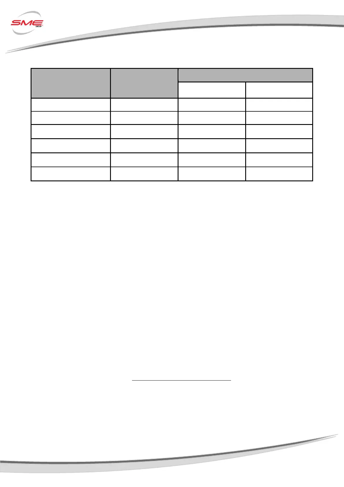
The following table shows you the most common cases:
Minimum Wire
Section Suggested
[mm
2
]
3.3 Main Contactor
The Controller must be connected to one Main Contactor for two basically reasons:
Capacitors Pre-Charge : The Controller handles all this phase internally by
discharging/charging its DC-Bus through the Key Input. As soon as a certain voltage value is
reached by the DC-Bus, the Controller can close the Main Contactor connecting it to the
Battery. In this way dangerous shocks on Controller's capacitors are avoided.
Safety: In case of dangerous situations, the Main Contactor must be opened disconnecting
the Battery from Controller. If the main contactor coil is not connected to the controller,
the system will not meet EEC safety requirements.
Sizing
In order to select the Main Contactor, it must be considered the Controller Ratings, the Duty Cycle
of the System and several other working conditions. The following empirical formula can be useful
to quickly find the Main Contactor minimum rating I
MC
:
with
 Loading...