ACM1_TAU_UserManual_En
Page 23 of 35
SME s.p.a. Via della Tecnica 40 Z.I.
36071 ARZIGNANO (VI) ITALY
Phone +39 0444 470511 - Fax +39 0444 451803
info@grupposme.com - www.grupposme.com
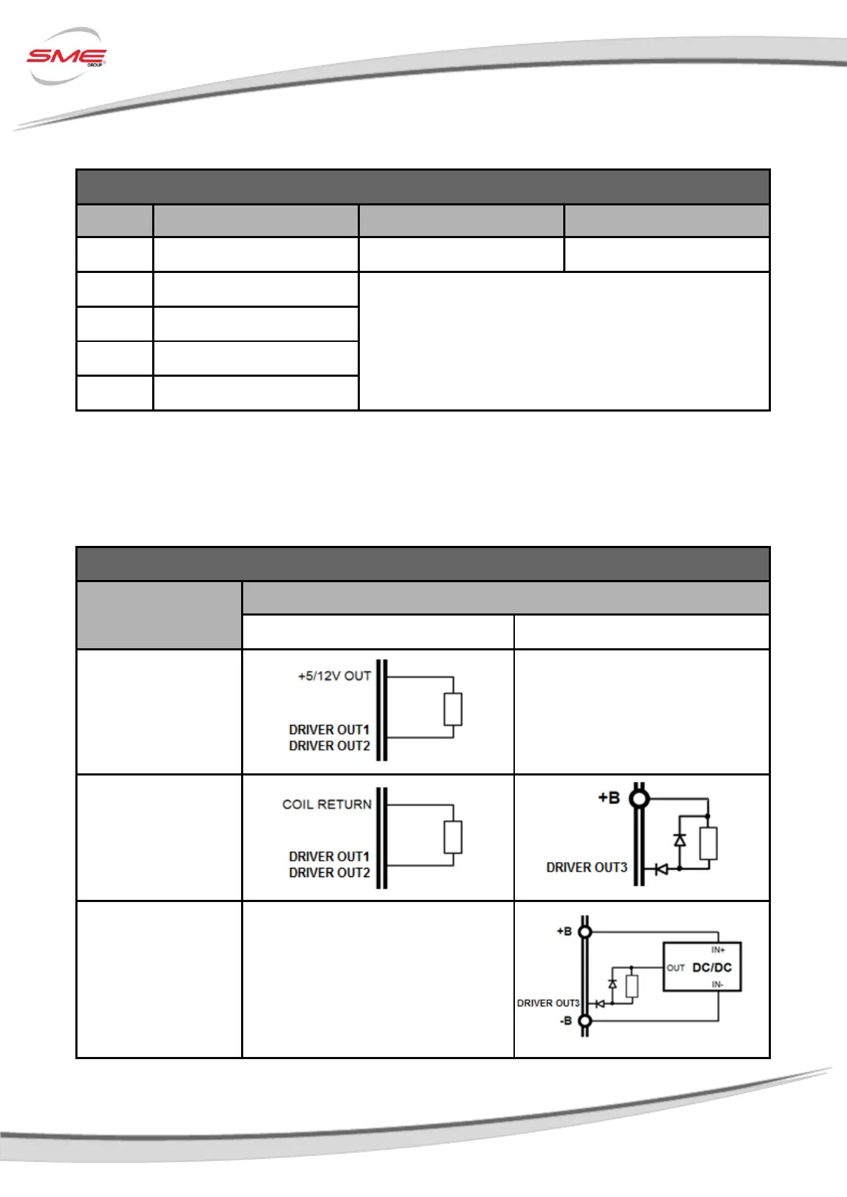
3.5.3 Driver Outputs (PWM)
Driver Outputs on Controller
Driver Output 2 (Max 1.5A)
Driver Output 3 (Max 1.5A)
Wiring
The Driver Output (low side output) is the negative reference applied to the load. The positive
reference is given by the other pin connected:
Driver Outputs Wiring on Controller
Driver Output 1 – Driver Output 2
External Supply from
a DC/DC converter
 Loading...