ACX1_TAU_SYNC_UserManual_En
Page 17 of 37
SME S.p.A. Via della Tecnica 40 Z.I.
36071 ARZIGNANO (VI) ITALY
Phone +39 0444 470511 - Fax +39 0444 451803
sales@sme-group.com - www.sme-group.com
Mounting and Replacement
The Controller meets IP65 environmental protection rating against dust and water.
The mounting location should be carefully chosen in order to be clean and dry, to minimize shock,
vibration, temperature changes and exposure to water & contaminants. If this kind of location
can’t be ensured, then a cover should be used to shield the controller. Cables must be routed to
prevent liquids flowing into the connections. The mounting location should also allow access to all
connections.
The replacement of the Controller must be done with the hand brake engaged, the drive wheels
off the ground, the key switch in off position, battery plug disconnected and the capacitors of the
inverter completely discharged.
The capacitors in the inverter can be discharged by connecting a load across the inverter’s +B and
–B terminals.
Cooling
It is recommended that the Controller is assembled to a flat, free of paint surface preferably lightly
coated with a thermal transfer compound using the 4 holes provided. Ideally, this surface will
provide maximum heat dissipation and ensure full rated power output. When designing a cooling
system, please refer to the following step:
1. Apply thermal grease to the Controller before mounting for better cooling effect.
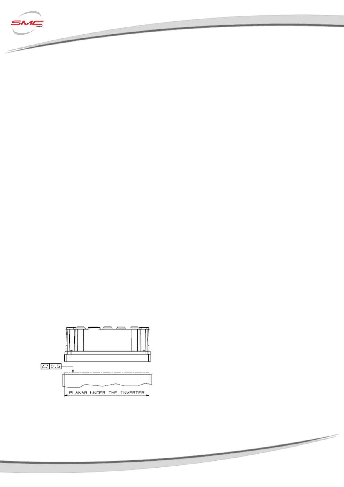
2. The Controller is cooled by the surface contact to the vehicle body, so it is important to pay
much attention to the flatness and the roughness of the surface of the vehicle frame where
it is mounted. The roughness R
z
should be between 1.6 μm and 3.2μm, while the planarity
of the surface should be under 0.5mm, as shown in the following image:
Planarity specifications for the AC-X1
with aluminium baseplate.
3.
Any airflow around the controller will further enhance the thermal performance.
 Loading...