28 - INSTALLATION 91477A460/B
The nozzles not provided are available at Authorised Service Centres.
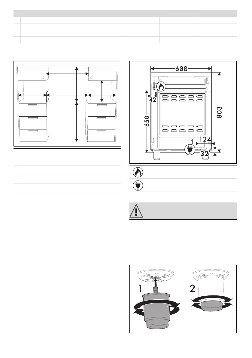
Appliance overall dimensions
1
Minimum distance from side walls or other
flammable material.
2
Minimum cabinet width (=A)
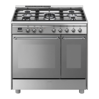
Appliance dimensions
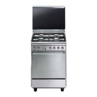
Levelling the appliance
The appliance must be level on the floor in order
to ensure greater stability.
After making the gas and electrical connections,
screw on the four legs supplied with the
appliance (1). Screw or unscrew the feet at the
bottom until the appliance is stable and level on
the floor (2).
7 Town gas G110 – 8 mbar AUX SR UR2
Rated heating capacity (kW) 1.0 1.8 3.4
Nozzle diameter (1/100 mm) 145 185 340
Pre-chamber (printed on nozzle) (/8) (/2) 0190
Reduced flow rate (W) 400 500 1200
A 600 mm
B 600 mm
C
1
min. 150 mm
D 873 ÷ 913 mm
H 750 mm
I 450 mm
L
2
600 mm
Position of gas connection
Position of electrical connection
See General safety instructions.