Do you have a question about the Smeg PGF75-4 and is the answer not in the manual?
This document serves as a comprehensive manual for a gas hob, providing instructions for both qualified installers and end-users. The appliance is designed for domestic use, specifically for cooking and heating food, and complies with current EEC directives. The manufacturer explicitly states that all other uses are considered improper and declines all liability for improper use.
The manual emphasizes that installation must be carried out by qualified personnel in accordance with current regulations. It also highlights the importance of keeping the manual in its entirety and in an accessible place for the entire working life of the hob. Users are advised to read the manual and all instructions before using the hob. A series of nozzles is supplied with the appliance and should be kept.
Regulations require the appliance to be earthed in accordance with electrical safety regulations. The plug connected to the power supply cable and the socket must be of the same type and conform to current regulations. The power socket must be accessible after the appliance has been built in. Users are warned never to unplug the appliance by pulling the power supply cable.
Immediately after installation, a brief inspection test of the appliance should be carried out. If the appliance does not function, it should be disconnected from the power supply, and the nearest technical assistance centre should be contacted. Users are strictly advised never to attempt to repair the appliance themselves.
Users are reminded to always check that the control knobs are in the "O" (OFF) position when they finish using the hob.
Packaging materials should not be left unattended in the home environment. Different waste materials from the packaging should be separated and delivered to the nearest collection centre for recycling. The appliance is marked according to European Directive 2002/96/EC on Waste Electrical and Electronic Equipment (WEEE), which frames European-wide validity for the return and recycling of waste electrical and electronic equipment.
The appliance data plate, containing technical data, registration number, and brand name, is positioned at a visible point under the safety cover. This data plate on the protective cover must never be removed.
Users are cautioned not to put pans with imperfectly smooth and flat bottoms on the hob panstand grids. Additionally, cooking receptacles that extend beyond the outside perimeter of the hob should not be used.
The appliance is designed for use by adults. Children should not be allowed to go near or play with it.
The manufacturer declines all liability for injury to persons or animals and for damage to property resulting from non-observance of the prescribed instructions, tampering with any part of the appliance, or the use of non-original spare parts.
The positioning of the hob requires building and/or carpentry work and must be carried out by a competent tradesman. Installation can be performed on various heat-resistant materials (T 90°C), including masonry, metal, solid wood, or plastic laminated wood.
An opening with specific dimensions (A: min 110 mm, B: min 460 mm, C: min 750 mm, D: 20-50 mm, E: min 50 mm, L: 700 mm, X: 492 mm, Y: 700 mm) must be created in the work surface. A gasket provided must be carefully positioned around the outer edge of the hole, ensuring it adheres properly and skims the hole on the front and rear sides. The hob is then placed on the insulating gasket and secured to the supporting structure using screws and fixing brackets, adjusting it until perfectly horizontal. Excess gasket edge should be trimmed. The brackets should not be fitted until the hob is in place.
This model also requires an opening with specific dimensions (A: min 110 mm, B: min 460 mm, C: min 750 mm, D: 20-40 mm, E: min 50 mm, L: 700 mm, X: 492 mm, Y: 700 mm). Additionally, a 3 mm deep cut in the worktop is required. Before positioning the hob, adhesive sponge material "E" must be placed over the milled surface. The hob is then placed on the cut in the worktop and secured using screws and fixing brackets, adjusting it until perfectly horizontal. The brackets should not be fitted until the hob is in place. A layer of "waterproof primer" should be applied to the milled surface.
Overall dimensions, including the location of gas and electrical connection points, are provided in millimeters. The bottom surface of the hob can become very hot, so under-bench access must be restricted to avoid hazards.
When installing the appliance above a cupboard, a dividing shelf (Max 150 mm high, Min 50 mm deep, Max 100 mm from the front edge) must be installed. This is not required if installed above an under-bench oven. Installation of an oven without a cooking fan underneath the hob is forbidden.
The voltage and capacity of the power supply cable must conform to the data on the plate under the protective cover. This plate must not be removed. The power supply cable plug and wall socket must be of the same type and conform to current electrical system regulations. The power line must be adequately earthed. An all-pole disconnect switch with a minimum contact gap of 3 mm, located in an easily accessible position near the appliance, must be installed on the power line. Reducers, adapters, or shunts should not be used.
If the power cable needs replacement, the wire section on the new cable must be at least 0.75 mm² (3 x 0.75 cable), with the earth wire (yellow-green) at least 20 mm longer. Only H05V2V2-F cable or similar, with a maximum temperature of 90°C, should be used. Replacement must be carried out by a specialized technician who makes the mains connections according to the provided diagram (L = brown, N = blue, = yellow-green).
The appliance must be installed only in rooms with permanent ventilation, as required by standards. The room must have sufficient air flow for normal gas combustion and necessary air exchange. Air intakes, protected by grills, must be appropriately sized and placed to prevent blockage. The room must be suitably ventilated to avoid overheating or excess humidity from cooking; after prolonged use, a window should be opened, or fan speed increased.
Discharge of combustion products must be guaranteed by hoods connected to a natural draught flue with certain efficiency or by forced aspiration. An efficient aspiration system requires careful planning by a qualified specialist, respecting prescribed positions and distances. After installation, the installer must issue a certificate of conformity.
Connection to the gas mains can be made with a rigid copper pipe or a flexible pipe conforming to standard regulations. After connection, check for leaks using a soapy solution. The hob is inspected for G20 natural gas (2H) at 20 mbar. For other gas types, refer to the "ADJUSTMENT TO DIFFERENT TYPES OF GAS" chapter. The hose connection at the rear of the appliance has a ½” internal thread (ISO 228-1).
The connection to the gas mains must not stress the appliance. It can be made using a biconical adapter D with the supplied gasket C.
Only flexible stainless steel pipes conforming to standard regulations should be used, inserting the supplied gasket C between fitting A and flexible pipe B. The flexible pipe must not exceed 2 meters in length and must not touch any moving parts or be crushed.
A pressure regulator should be used, and the connection to the tank made according to standard regulations. Feed pressure must conform to the levels in the "Burner and nozzle characteristics table."
Before any cleaning or maintenance, unplug the appliance from the mains. The hob is factory-set for natural gas G20 (2H) at 20 mbar. For other gas types, burner nozzles must be changed, and the minimum flame adjusted on the gas taps.
This table provides specifications for different burner types (Auxiliary, Semi rapid, Ultra Rapid) for LPG (G30/G31 30/37 mbar) and Natural gas (G20 20 mbar). It includes:
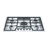
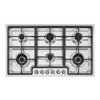
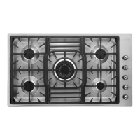
A diagram illustrates the arrangement of burners:
After adjustments, remount parts in reverse order of nozzle replacement. If the device is regulated for a gas type other than the one tested, replace the label on the guard with the corresponding new gas label, available from an Authorized Assistance Centre.
Light the burner and set it to minimum. Remove the knob and turn the regulation screw (inside or next to the gas tap pin, depending on the model) until a suitable minimum flame is achieved. Replace the knob and check burner flame stability (the flame should not go out when quickly turning the knob from maximum to minimum). Repeat for all gas taps.
To regulate the minimum for LPG, fully tighten the screw inside or next to the gas tap pin (depending on the model) in a clockwise direction. By-pass diameters for each burner are in the "Burner and nozzle characteristics table."
If gas taps become blocked and hard to turn over time, they should be cleaned inside and re-greased. This operation must be performed by an authorized person.
Before turning on burners, ensure flame-spreader crowns and caps are properly fitted. Flame-spreader holes A must align with ignition plugs and thermocouples. To prevent damage to the worktop, a raised pan stand H is provided for pans larger than those specified in "Pan diameters." Pans larger than 28 cm must be used only on the central burner. The pan stand H can also be used with woks. A symbol next to each knob indicates the relative burner. The device has electronic ignition. Press and turn the knob counter-clockwise to the high flame symbol until the burner ignites. For models with a safety valve, hold the knob down for a few seconds after ignition to allow the thermocouple to heat up. If the burner goes off when the knob is released, the thermocouple has not heated sufficiently. Wait and repeat, holding the knob longer. This is not needed for burners without thermocouples. Once ignited, adjust the flame as required. Always check knobs are in the "O" (off) position when finished. If burners accidentally turn off, a safety device will trip after about 20 seconds to cut off gas flow.
For better use and lower gas consumption, use covered cooking receptacles with flat, smooth bottoms, proportional to the burner size to prevent flames from licking the sides (see "Pan diameters"). When water boils, lower the flame to prevent boiling over. To avoid burns or worktop damage, all receptacles must be within the hob's perimeter. Be extremely careful when using fats or oils to prevent overheating and fire.
The manual provides minimum and maximum pan diameters (in cm) for each burner type:
Before any intervention, disconnect the appliance from the mains. Never use a steam jet to clean the appliance.
To maintain good condition, clean stainless steel regularly after use, once it has cooled.
For easier cleaning, the pan stand, caps, flame-spreader crowns, and burners are all removable. Wash them with warm water and non-abrasive detergent, removing stubborn food residues. Wait for all parts to be fully dry before remounting. Refit caps on their respective flame-spreader crowns, ensuring notches A align with burner pins B. Ignition plugs and thermocouples must always be very clean. Check them frequently and clean with a wet cloth if necessary. Remove any dry residue with a toothpick or needle.
In models with a central pan stand, fit this piece, ensuring its centre is perfectly aligned with the burner's centre.