36 - INSTALLATION 91477A696/B
The nozzles not provided are available at Authorised Service Centres.
Electrical connection
General information
Check the mains characteristics against the data
indicated on the plate.
The identification plate bearing the technical
data, serial number and brand name is visibly
positioned on the appliance.
Do not remove this plate for any reason.
The appliance must be connected to ground
using a wire that is at least 20 mm longer than
the other wires.
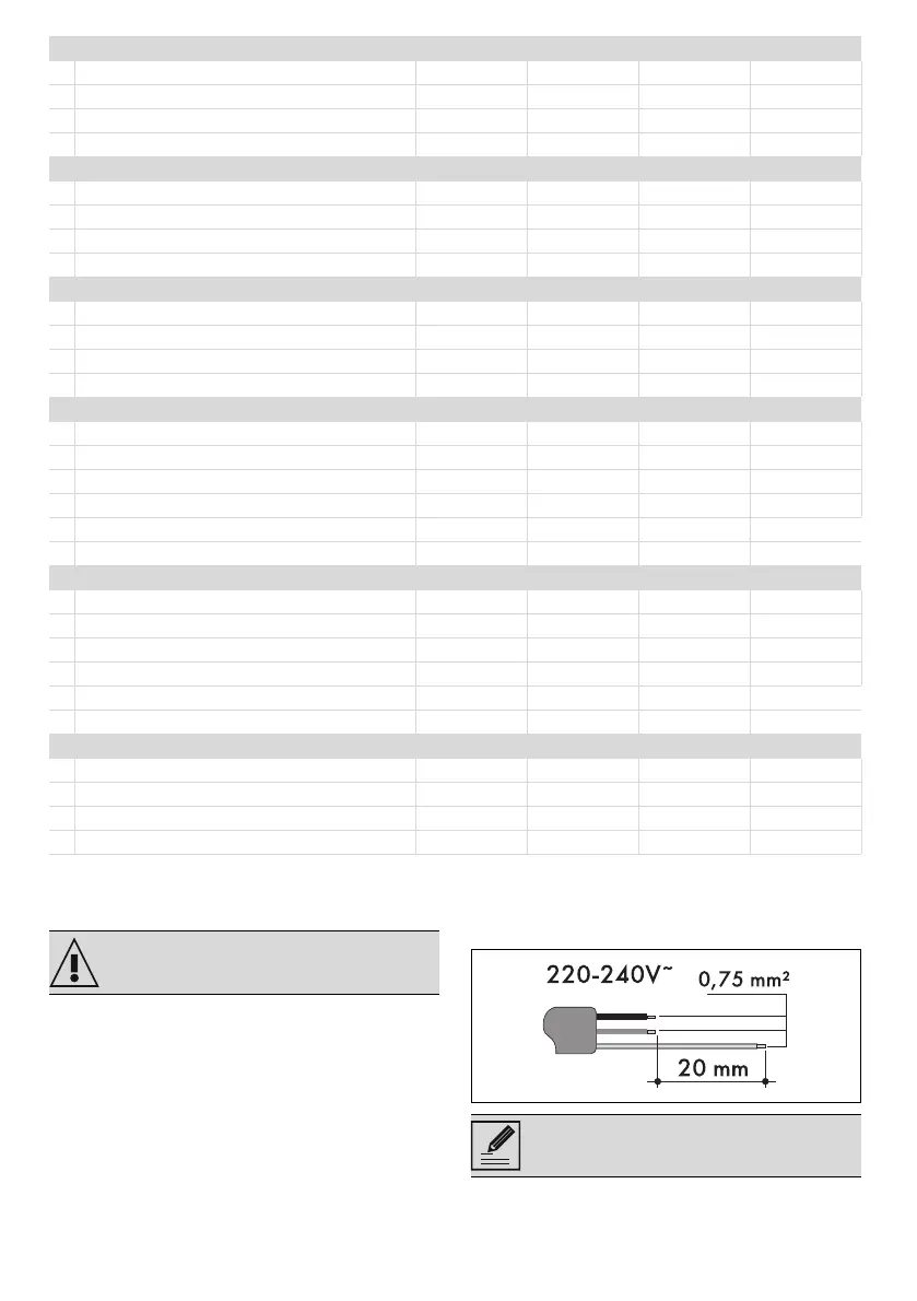
The appliance can work in the following modes:
• 220-240 V 1N~
Fixed connection
Fit the power line with an all-pole circuit breaker
2 Natural Gas G20 - 25 mbar AUX RR UR2 ext. UR2 int.
Rated heating capacity (kW) 1.05 2.5 4.1 0.9
Nozzle diameter (1/100 mm) 72 103 145 65
Pre-chamber (printed on nozzle) (X) (Y) (H3) (H1)
Reduced flow rate (W) 400 800 1200 400
3 Natural Gas G25.1 - 25 mbar AUX RR UR2 ext. UR2 int.
Rated heating capacity (kW) 1.05 2.5 3.9 0.9
Nozzle diameter (1/100 mm) 77 115 148 72
Pre-chamber (printed on nozzle) (F1) (F3) (F3) (H1)
Reduced flow rate (W) 400 800 1200 400
4 Natural Gas G2.350 - 13 mbar AUX RR UR2 ext. UR2 int.
Rated heating capacity (kW) 1.0 2.4 3.8 0.9
Nozzle diameter (1/100 mm) 94 148 200 91
Pre-chamber (printed on nozzle) (Y) (F3) (H1) (Y)
Reduced flow rate (W) 400 800 1400 400
5 LPG G30/31 - 30/37 mbar AUX RR UR2 ext. UR2 int.
Rated heating capacity (kW) 1.05 2.5 4.1 0.9
Nozzle diameter (1/100 mm) 50 79 100 44
Pre-chamber (printed on nozzle) - (Z) - -
Reduced flow rate (W) 400 800 1400 400
Rated flow rate G30 (g/h) 76 182 298 65
Rated flow rate G31 (g/h) 75 179 293 64
6 LPG G30/31 - 37 mbar AUX RR UR2 ext. UR2 int.
Rated heating capacity (kW) 1.1 2.5 4.0 0.8
Nozzle diameter (1/100 mm) 50 75 96 42
Pre-chamber (printed on nozzle) - (Z) (S4) -
Reduced flow rate (W) 450 800 1500 450
Rated flow rate G30 (g/h) 80 182 291 58
Rated flow rate G31 (g/h) 79 179 286 57
7 Town gas G110 – 8 mbar AUX RR UR2 ext. UR2 int.
Rated heating capacity (kW) 1.05 2.5 3.4 1.0
Nozzle diameter (1/100 mm) 145 230 300 145
Pre-chamber (printed on nozzle) /8 /3 - (X)
Reduced flow rate (W) 400 800 1000 400
See General safety instructions.
The values indicated refer to the cross-
section of the internal conductor.