8 SERIES BOILER INSTALLATION AND OPERATING INSTRUCTIONS
Page 6
A qua s tat
T he r mo m ete r
R e d u c i n g V a l ve
P re s s ur e
P um p
B a l a n c e V a l ve
B ac k f l o w - P re v en t i on
De v i ce
E xp a nsion
Ta n k
P re s s ur e
Rel i e f V a l ve
Che c k V a l ve
N O T ES :
1 . B o il e r c ir cu it p i p i ng m us t be s i z ed large enough to handle
m ax i m u m fl o w through unit .
2. Boiler pump sized to boiler d es i gn fl o w r equirements .
3. All boilers furnished with f ac t ory m ounted water
t e m pe r a t u
r e / pressuregauge .
4. A plug valve will allow the best fl o w control for the bypass .
A ba ll va l ve m ay no t be su it a ble and may create noise .
Notice: These drawings show sugge s t ed p i p i ng c onfiguratio n
and valving. Check with local c odes and ordinances for
specific req u i r e m en t s .
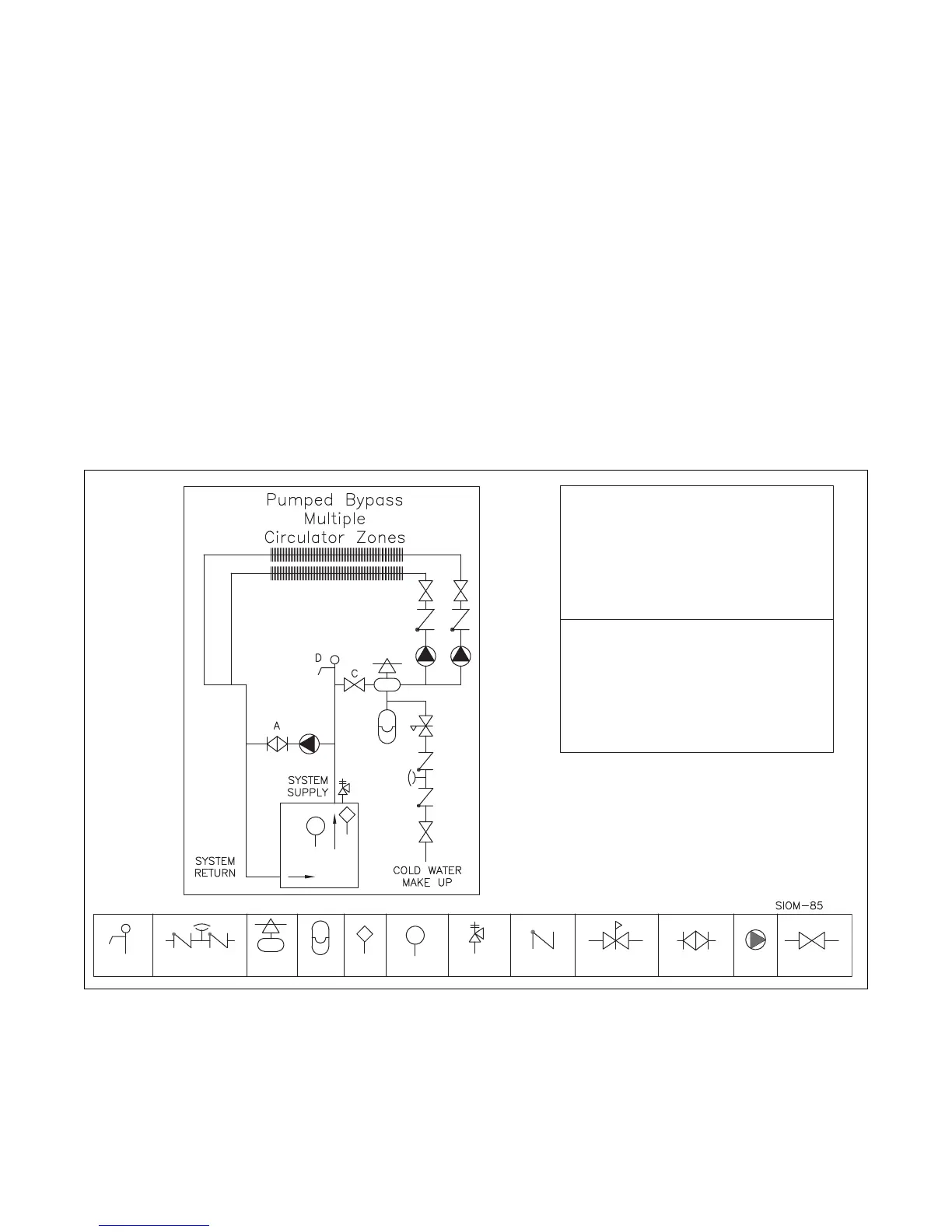
1. Tu r n boiler on and c l ose valve A .
2. After steady-state operation, if T 1 i s l ess than 130° F
slowly open valve A until T1 cl i m bs t o desired operatin g
t e m pe r a t u r e above 130° F.
3. Check after system opera t i ng t e m pe r a t u r e
ha s
s tabilized. Make fi na l ad j us t m en t s .
Bypass Adjustment Procedu r e T o M a i n t a i n I n l e t
Te m pe r a t u r e A b ove Dew Point
T1 = Te m p M i n = 130° F
Drain Cock
B a l l o r G a te
V a lv e
S ys t e m P u r g i ng .
1. Close valv e A and C .
2. Attach a short hose to valve D and submerge in bucke t
o f w a ter. O p en V a l ve D .
3. Manually open the fill valve a nd use the domestic wate r
system pressure to purge
air fr o m each zone one at a
time. W hen air bubbles stop fl o w i ng fr o m t he hos e
close va l ve D .
4 . R es t fill va l ve t o au t o m a ti c fill, and open v al v e s A and C .
A i r V e n t &
S epa r ato r
Figure No. 5 – Pumped Bypass
PIPING
Pumped Bypass
For these systems that may experience condensation,
an additional circulator and balancing valve can be
used to provide a return water temperature blend. This
method works well with systems with multiple zones
with circulators, see Figure 5. The dedicated bypass
circulator provides a strong blending flow without
diminishing the fl ow available to any heating zone. Any
residentially sized circulator is adequate for this purpose.
The balancing valve allows for adjustment of the return
temperature (see adjustments procedure in Figure 5).
Pump Away Bypass
For systems that use a single circulator to pump away
from the boiler, the bypass should be installed on the
discharge side of the circulator, see Figure 6. Full
temperature water supplies the baseboard distribution
system as before. Half of the circulator’s volume moves
through the bypass, blending and heating the cooler
return water. Again, the cost of installing the bypass is
small and setting it by temperature can be accomplished
with a contact thermometer (see bypass adjustment
procedure Figure 6).