8 SERIES BOILER INSTALLATION AND OPERATING INSTRUCTIONS
Page 7
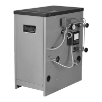
Reverse Acting Aquastats
There is an alternative for existing systems experiencing
condensation that does not require re-piping the boiler.
It is very effective on single zones high mass systems
with large water volumes and cast iron radiation. This
option utilizes a reverse acting aquastat, one that makes
on temperature rise. Wired in series with the circulator,
this control allows the burner to fi re while holding the
circulator off until the boiler reaches an acceptable
temperature. It then starts the system circulation again,
see Figure 7.
The most commonly available reverse acting aquastat is
a Honeywell L4006B. The aquastat should be mounted
in an immersion well directly installed in the boiler. The
use of heat conductive grease, Honeywell part #972545,
in the immersion well is strongly recommended for
fast and accurate temperature response. Set this
adjustable aquastat to make at no less than 130°F.
While this method can cause the circulator to cycle
more frequently, setting the aquastat’s differential to the
maximum 25-30°F will minimize short cycling.
Figure No. 7 – Reverse Aquastat
Each of these bypass solutions also has the added
benefi t of increasing circulation in the boiler which will
maximize tankless coil output and increase the accuracy
of temperature sensing controls.
reverse
aquastat
N.O.
T
T
t'stat
GV
115 volts
24 volts
circulator
operating
aquastat
N.C.
REVERSE
AQUASTAT
SET AT 130° F
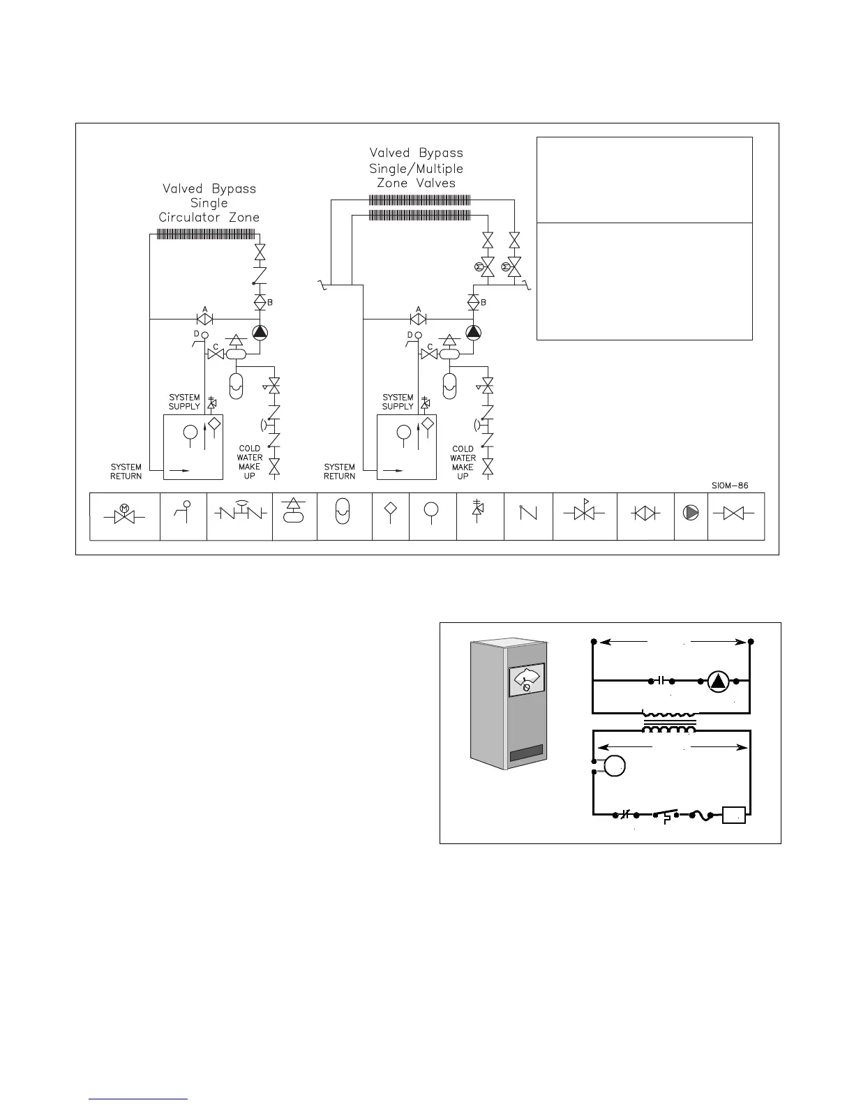
Figure No. 6 – Pump Away Bypass
Aquastat Thermometer
Reducing Valve
Pressure
Pump
Balance Valve
1. Turn boiler on and open valves A & B.
2. After steady-state operation, if T1 is less than 130° F
slowly close valve B until T1 climbs to desired operating
temperature above 130° F.
3. If T1 is greater than desired operating temperature, slowly
close valve A to adjust to lower desired temperature above
130° F.
4. Check after system operating temperature has
stabilized. Make final adjustments.
Bypass Adjustment Procedure To Maintain Inlet
Temperature Above Dew Point
T1=Temp Min=130° F
Backflow-Prevention
Device
Expansion
Tank
Pressure
Relief Valve
Check Valve
NOTES:
1. Boiler circuit piping must be sized large enough to handle
maximum flow through unit.
2. Boiler pump sized to boiler design flow requirements. A
percentage of the pump capacity is used for the bypass blend.
3. All boilers furnished with factory mounted water
temperature/pressure gauge.
4. A plug valve will offer the best flow control for the bypass. A ball
valve may not be suitable and may create noise.
Notice: These drawings show suggested piping configuration
and valving. Check with local codes and ordinances for
specific requirements.
Motorized Valve
Drain Cock
Ball or Gate
Valve
Air Vent &
Separator
System Purging.
1. Close valve A and C.
2. Attach a short hose to valve D and submerge in bucket of
water. Open Valve B and D.
3. Manually open the fill valve and use the domestic water
system pressure to purge air from each zone one at a time.
When air bubbles stop flowing from the hose close valve D.
4. Rest fill valve to automatic fill., and open valves A and C.