17
INSTALLATION AND OPERATING INSTRUCTIONS
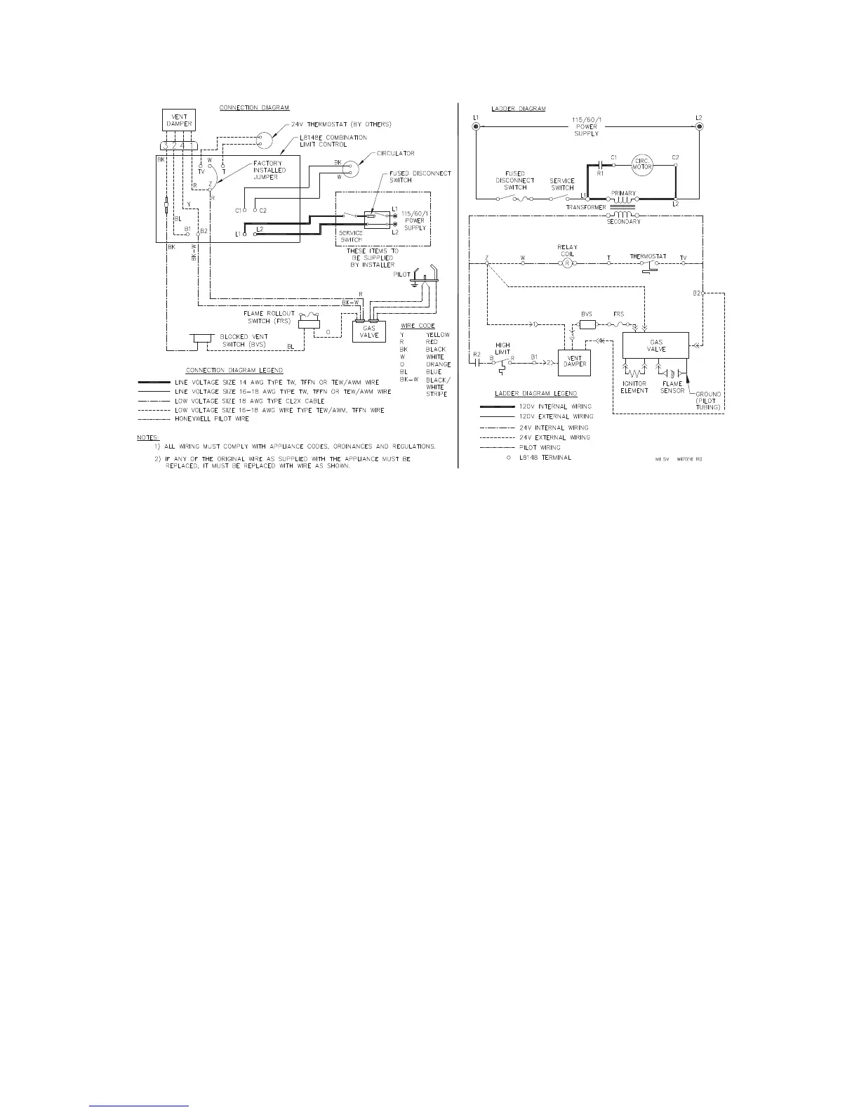
2. Intermittent Ignition (see Figure 6.3 above)
a. The vent damper is continuously powered. On a
call for heat, limit relay R is energized, which
energizes:
●
the circulator (when used) through contact
R1, and
●
the vent damper operator through contact R2,
provided that the high-limit aquastat switch is
closed.
The damper operator opens the vent damper.
b. Once the damper is proven open, the ignition
circuit within the gas valve energizes, provided
that all of the following conditions are met:
●
the blocked vent switch is closed, and
●
the flame rollout switch is closed.
c. When the call for heat ends:
●
Limit relay R de-energizes, which opens
contacts R1 and R2.
●
The circulator shuts down.
●
The gas valve de-energizes.
●
The vent damper closes.
d. If temperature exceeds limit setting, main burners
shut off and circulator continues to operate.
Figure 6.3: Wiring and Connection Diagram – Intermittent Ignition