ED-X Display Installation
Decide on a location.
Allow adequate clearance behind the unit for the cable connection to ensure the cable is not
unduly stressed.
Ensure that there is sufcient length of cable to remove unit for servicing purposes.
Using the supplied template as a guide, cut out the hole for the back and drill four 4.3 mm (0.170”)
holes for the studs.
Screw the four M4 studs into the rear of the unit.
Connect the cable into the rear of the unit.
Place the unit in position, then secure it by screwing the thumb nuts onto the studs.
1.
2.
3.
4.
5.
6.
7.
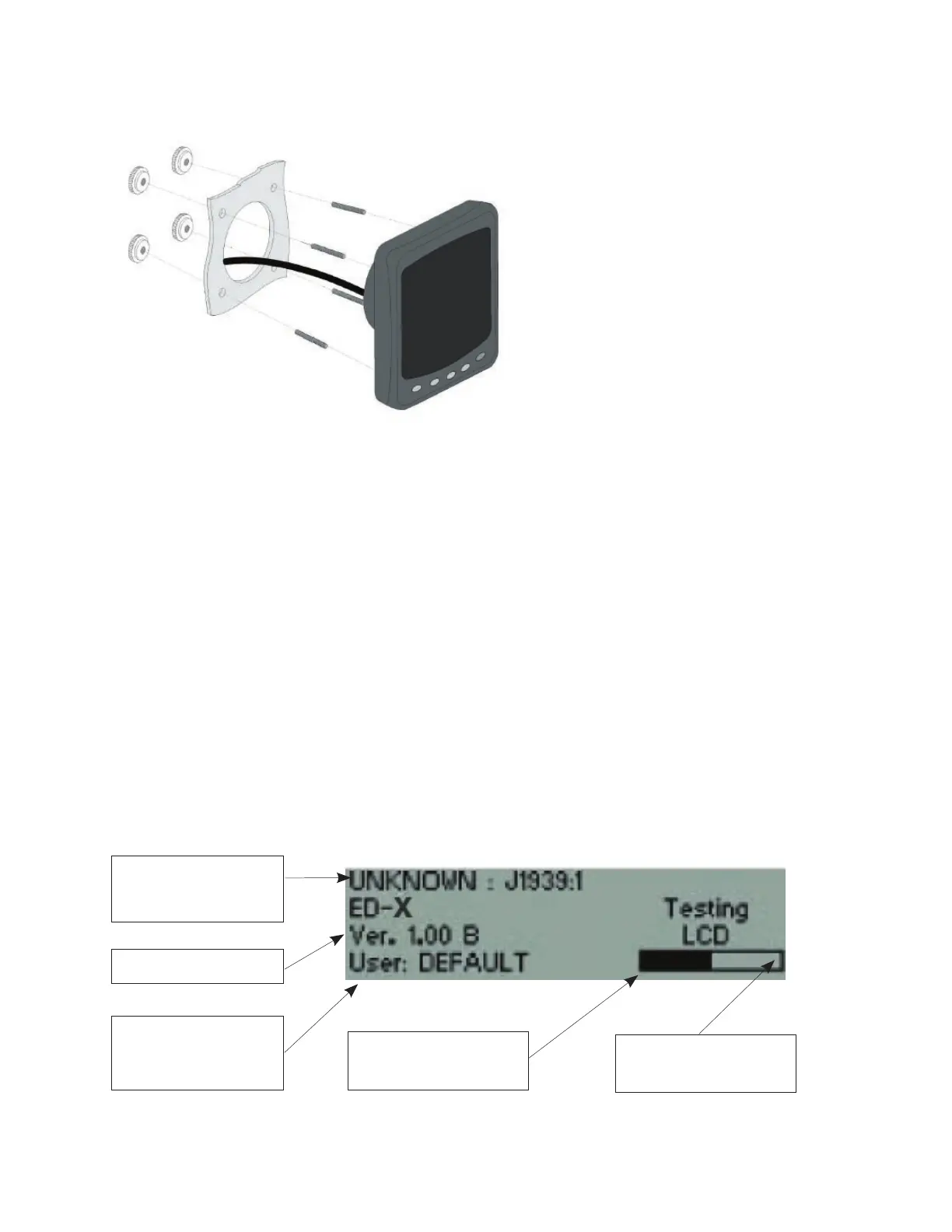
Power On Screen
This power on screen will be shown when power is rst applied to the unit. The display will
perform a self-test for proper operation of the datalink, ash, RAM and LCD. A progress
bar gives a general indication of how far the self-test has progressed. The display also
indicates the current user for whom the display is congured.
Engine Configuration,
Comms Protocol and
Engine source
Software Version
Shows the current user
for whom the display is
configured
Bar indicating how far the
self-test has progressed
Parameters tested by the
display