snapnrack.com
17
MLPE & RSD Installation
INSTALLATION INSTRUCTIONS - SNAPNRACK MLPE FRAME ATTACHMENT KIT
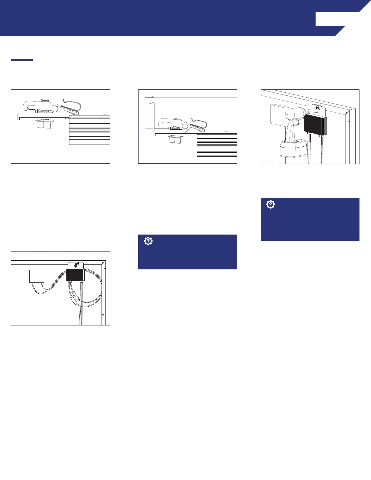
1) Slide the backplate channel of the
MLPE device under the MLPE Frame
Attachment Kit bolt. The MLPE
mounting plate should rest against
the MLPE mounting plate backstop
on the MLPE Frame Attachment Kit.
2) Position the MLPE Frame
Attachment Kit on the module
frame flange in a location that
will not interfere with mounting
system components. The module
frame flange should rest against
the module flange backstop on the
MLPE Frame Attachment Kit.
3) Tighten the mounting bolt on the
MLPE Frame Attachment Kit to 12
lb-ft (144 lb-in).
Avoid blocking module frame
drainage holes when installing the
MLPE Frame Attachment Kit.
Install Note:
4) Connect the module leads to
the input connectors on the MLPE
device and manage conductors with
the integrated Smart Clip.
The MLPE Frame Attachment Kit
bonds the following components:
Module Frame, MLPE backplate and
Smart Clip.
Install Note:
SnapNrack MLPE Frame Attachment kit are used to attach module level performance enhancing devices, and other devices such
an SRD (rapid shutdown device), directly to module frames, and provide integrated grounding/bonding for Devices grounded
through metal back plate. (Refer to the list of tested MLPE devices on page XX of this manual).
 Loading...