snapnrack.com
7
Site Survey
ò
Measure the roof surfaces and develop an accurate drawing,
including any obstacles such as chimneys and roof vents.
ò
If plans for the roof structure are available, verify that the
plans match the fi nal structure.
ò
Identify any roof access or setback areas as required by the
local AHJ.
ò
Identify any construction issues that may complicate the
process of locating rafters from the roof surface.
ò
If you fi nd structural problems such as termite damage or
cracked rafters that may compromise the structure’s integrity
consult a structural engineer.
Pre-Installation Requirements
Design Guidance
ò
PV Designers should account for the 0.75 inch spacing
between rows and columns of modules when creating the layout.
ò
Determine site conditions for calculating the engineering
values, confi rm site conditions and code versions comply with
local AHJ requirements.
ò
Reference site conditions and system specifi cations in
TopSpeed™ Structural Engineering Report to determine the
number of attachments per module side.
ò
Insert SnapNrack installation details into design plan set
specifi c to the project requirements.
ò
Draw roof attachment locations on plan set layout based on
TopSpeed™ Structural Engineering.
ò
Identify homerun and Junction Box locations based on
rooftop wiring requirements.
ò
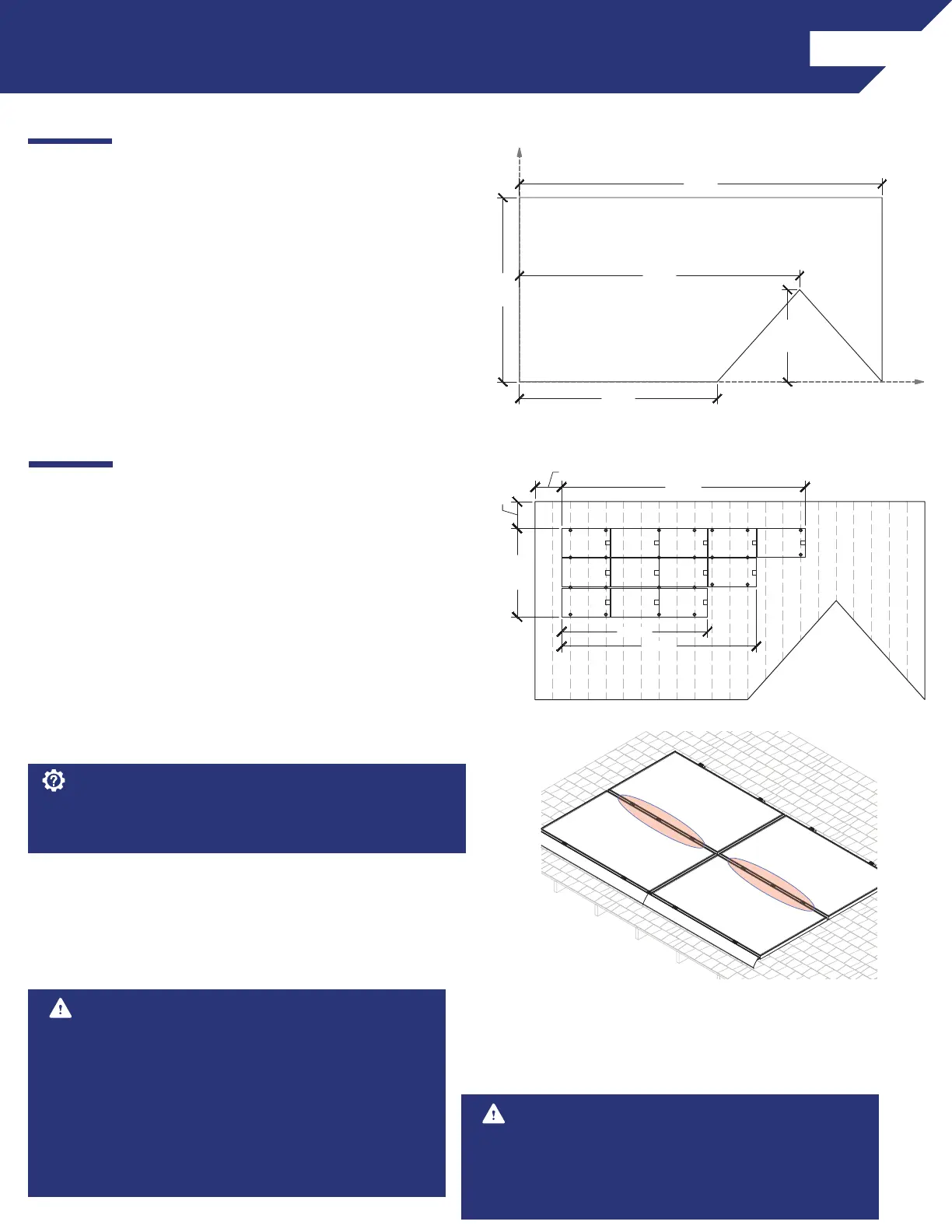
Mark distance from array edge to identifi able roof feature in x
and y axes.
X-AXIS
Y-AXIS
22'-4"
44'-0"
11'-2"
24'-0"
34'-0"
3'-0"
3'-0"
(+)
(-)
(+)
(-)
(+)
(-)
(+)
(-)
(+)
(-)
(+)
(-)
(+)
(-)
(+)
(-)
(+)
(-)
(+)
(-)
(+)
(-)
(+)
(-)
27'-6"
22'-0"
16'-6"
10'-0"
Image note: X-Axis described in this manual is cross-slope
on the roof, Y-Axis is in line with the roof slope.
Safety Guidance
ò
Always wear appropriate OSHA approved safety
equipment when at active construction site.
ò
Appropriate fall protection or prevention gear should be
used. Always use extreme caution when near the edge of a
roof.
ò
Use appropriate ladder safety equipment when accessing
the roof from ground level.
If environmental load conditions require three TopSpeed™ attach-
ments per module side this is only required when modules share
attachments.
Best Practice:
Image note: This four module array is installed in a high load
confi guration with three attachments per side where two
modules share attachments. See highlighted area. As shown,
three attachments are never required at the skirt or the top
of the array.
Safety Guidance Continued
ò
Safety equipment should be checked periodically for wear
and quality issues.
ò
Always wear proper eye protection when required.