snapnrack.com
22
Grounding Specifi cations
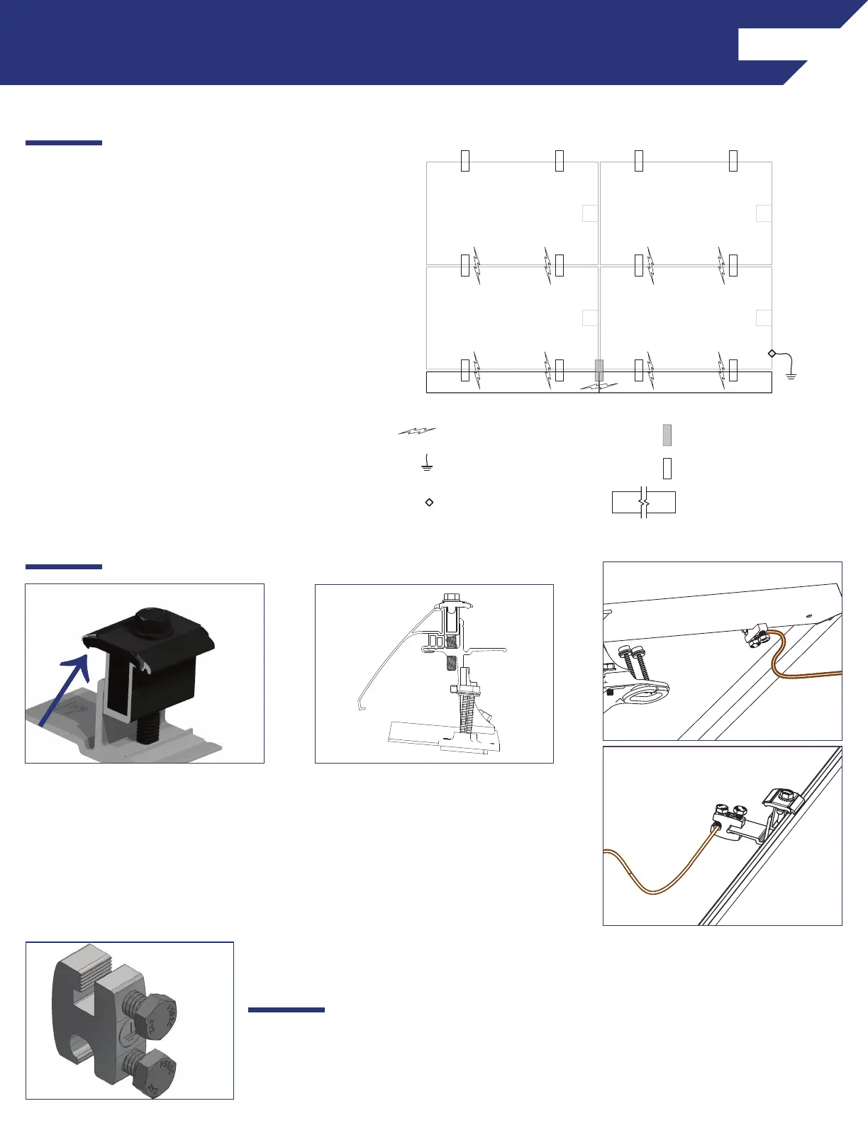
GROUND PATH DETAILS
All TopSpeed
TM
components in the fault current
ground path have been Certifi ed to be used
multiple times for grounding/bonding. The
UL 2703 Listing does not specify a maximum
number of uses for the Mount, Link, or Ground
Lug. Review the requirements of the National
Electrical Code (NEC) Article 250 to select the
appropriate Equipment Grounding Conductor
size based on the short-circuit current of the PV
system.
When using Ground Lug R the following
components are part of the fault current ground
path:
• SnapNrack, TopSpeed™ Mount
• SnapNrack, TopSpeed™ Clamp
1) Row to row module bonding
provided by bonding clips in Mount
assembly and Clamp assembly.
2) Column to column bonding
provided by Universal Skirt and
bonding clips in the Clamp assembly
and/or the RL Universal Link
assembly.
Module heights evaluated for
bonding with Link Bonding Clamps:
40mm, 38mm, 35mm, 32mm, 30mm
3) Each continuous array is
connected to Equipment Grounding
Conductor through Ground Lug
(242-92202) installed on one module
per array.
Optionally; Install Ground Lug on the
Mount Landing Pad at the top of the
array.
GROUNDING METHOD DETAILS
GROUNDING MARKING DETAILS
The Ground Lug is marked with the
ground symbol.
GROUND PATH
EQUIPMENT GROUNDING
CONDUCTOR
(+)
(-)
(+)
(-)
(+)
(-)
(+)
(-)
TO EGC
ARRAY SKIRT
GROUND LUG
TOPSPEED™ MOUNT
TOPSPEED™ CLAMP
 Loading...