Section 4 - REPAIR & ADJUSTMENTS
WARNING
DO NOT attempt any adjustments, maintenance or
service with the engine or blade running. STOP
blade. STOP engine. Remove spark plug wire from
spark plug and secure wire away from spark plug.
Engine and components can be extremely hot. Avoid
burns by allowing engine and components sufficient
time to cool.
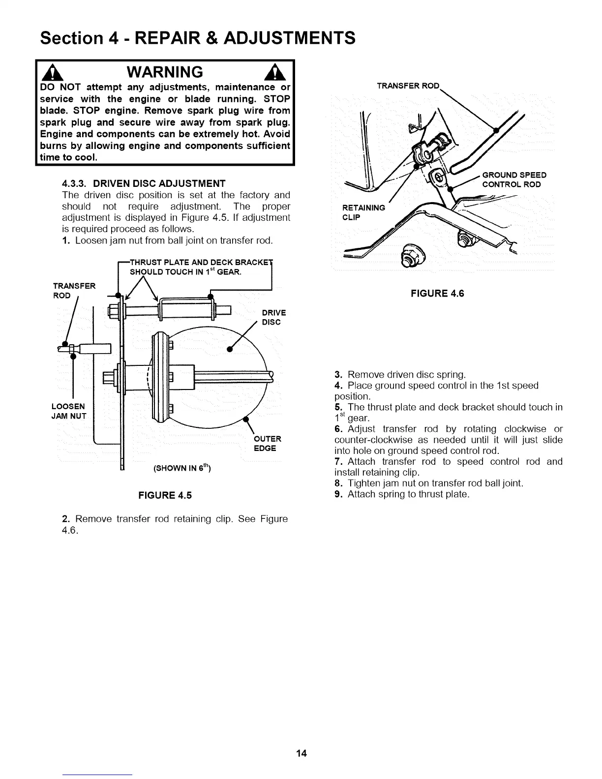
4.3.3. DRIVEN DISC ADJUSTMENT
The driven disc position is set at the factory and
should not require adjustment. The proper
adjustment is displayed in Figure 4.5. If adjustment
is required proceed as follows.
1. Loosen jam nut from ball joint on transfer rod.
TRANSFER
ROD /
LOOSEN
JAM NUT
mTHRUST PLATE AND DECK BRACKE'I[
SHOULD TOUCH IN 1st GEAR. |
!
EDGE
(SHOWN IN 6th)
FIGURE 4.5
2. Remove transfer rod retaining clip. See Figure
4.6.
TRANSFER ROD
GROUND SPEED
CONTROL ROD
RET_NING
CLIP
FIGURE 4.6
3. Remove driven disc spring.
4. Place ground speed control in the 1st speed
position.
5. The thrust plate and deck bracket should touch in
1stgear.
6. Adjust transfer rod by rotating clockwise or
counter-clockwise as needed until it will just slide
into hole on ground speed control rod.
7. Attach transfer rod to speed control rod and
install retaining clip.
8. Tighten jam nut on transfer rod ball joint.
9. Attach spring to thrust plate.
14