Maintenance(Continued)
WARNING
DONOTattempt any maintenance,adjustments or service
with engine and blade running. STOPengineand blade.
Disconnectspark plug wire and secure awayfrom spark
plug. Engineand components are HOT.Avoid serious
burns, allow sufficient time for all components to cool.
BladeSharpening(Continued)
4. Sharpenthe bladeon a grinding wheelat an angle of 22
to 28 degrees (B, Figure 23). DO NOTsharpen the blade
beyondthe original cutting edge(A).
Do not sharpen
beyondoriginal
cutting edge
Endview of
bladeassembly
Figure23: Sharpening the mower blade
5. Check bladefor balance.If necessary,correct balanceby
grinding heavyend of blade.
6. Reinstall blade(B, Figure 22}. Notethe correct
assembly order:
(A) Blade hub
(B) Blade
(C) Bladeflange (facing up)
(D) Conewasher (concaveside up)
(E) Capscrew
7. Checktorque of blade retainingcap screw.
Recommendedtorque should be 40 ft. Ibs.
WheelDriveControlAdjustment
(Self-PropelledModelsOnly)
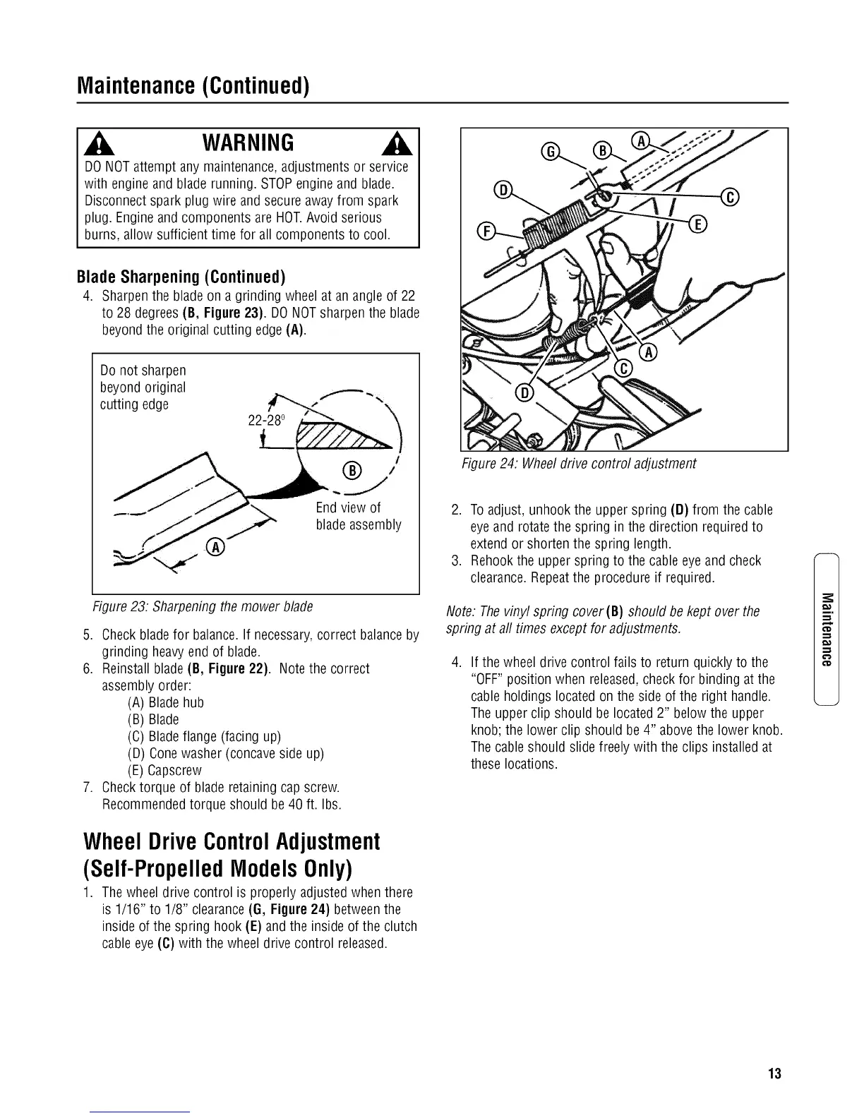
1. The wheel drive control is properly adjusted when there
is 1/16" to 1/8" clearance(G, Figure24) betweenthe
inside of the spring hook (E) and the inside of the clutch
cableeye (C) with the wheeldrive control released.
Figure24: Wheeldrive control adjustment
2. To adjust, unhook the upper spring (D) from the cable
eyeand rotatethe spring in the direction required to
extend or shorten the spring length.
3. Rehook the upper spring to the cable eyeand check
clearance.Repeatthe procedure if required.
Note. Thevinyl spring cover(B) should be kept over the
spring at aft times except for adjustments.
.
If the wheel drive control fails to return quickly to the
"OFF" position when released,checkfor binding at the
cable holdings located on the side ofthe right handle.
Theupper clip should be located 2" below the upper
knob; the lower clip should be 4" above the lower knob.
Thecable should slide freely with the clips installed at
these locations.
m.
€'D
13
 Loading...