2
3
4
5
14
13
12
11
10
9
8
7
1
6
3
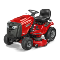
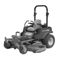
This operator manual describes the Snapper Zero
Turn Rider. The rider is tted with a four-stroke
overhead valve engine.
Transmission from the engine is made via
belt-driven hydraulic pumps. Using the left and
right steering controls, the ow is regulated and
thereby the direction and speed.
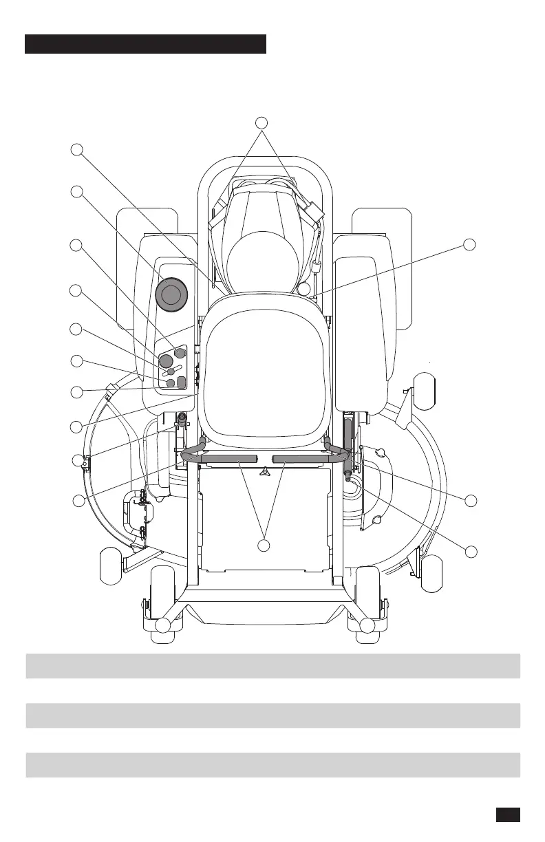
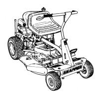
1. Motion control levers 6. Fuel shut o 11. Choke control
2. Park brake 7. Fuel tank 12. Service meter
3. Tracking bolts 8. Blade switch 13. Seat adjustment
4. Fuse 9. Ignition switch 14. Deck lift
5. Bypass linkages 10. Throttle control
11
CONTROLS