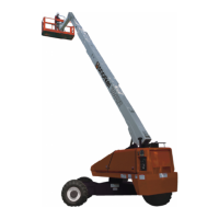
Page 4 A38E Work Platform
Section
1.1
Introduction & Specications
DRIVE & STEER SYSTEMS
The A38E Work Platform is restricted to low speed
drive when the Platform is raised above the Boom
Rest Limit Switch. The Traction controller controls
the application of drive from the Joystick by means
of two Traction Motors, which are assembled to the
drive wheels via a Drive Reduction Gearbox.
Steering of the A38E Work Platform is controlled by
the P600, which controls the signals activating a
double acting cylinder. An Operator can Steer left or
right by depressing the Rocker Switches on top of
the Joystick, while activating the Interlock Switch.
POWER SYSTEM
The power system incorporates eight 6V batteries
driving the drive traction motors, or the 4kW (5.4HP)
electric motor which in turn drives the hydraulic
pump. The application of this hydraulic pressure is
performed by the Control System.
CONTROL SYSTEM
The machine is provided with fully proportional
controls by means of the interaction between
a P600, electronic motor controller and a
proportional joystick. The P600 and motor controller
regulate the drive motor/pump speed and hence the
ow of oil reaching the cylinders, the Worm Drive
Unit or the Drive Reduction Gearbox. It regulates
the direction of ow of the hydraulic oil via the
solenoid valves located on the manifold block, and
it also monitors the operation of all switches on the
machine via the machine harness system.
The motor control units are located, in the left hand
chassis module. The manifold block is located on the
hydraulic tank. This is accessible by removing the
main cover.
CHASSIS
The chassis is a structural frame designed to support
all the components of the A38E Work Platform.
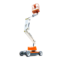
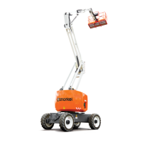
A38E PURPOSE & LIMITATIONS
The purpose of the A38E work platform is to provide
a quickly deployable variable height work platform.
It is capable of lifting two people with work tools
up to an upper limit of 215 kg (ANSI 475 lbs) in
total. The unit will provide the ability to reach over
obstacles but must be used on rm level ground.
See Specication table on page 1-3.
The platform must only be used on rm level or
slightly uneven ground capable of supporting the
maximum load generated under the four wheels. Do
not use on soft or severely sloping ground.
A DANGER A
NOTE: It should be recognised that if the tilt
switch senses a degree of slope greater than
3º the elevating circuits will lockout and sound
a warning alarm. The Emergency Override
should then be used, to lower the Elevating
Assembly.
SNORKEL GUARD OVERRIDE
SWITCH
When the Snorkel Guard system is activated, the
Snorkel Guard override switch is used to override
the system to operate Upper and Lower Boom down
functions. The switch is spring returned to the normal
operation position.
• Hold the switch upward to override the Snorkel
Guard System.
• Release the switch to the downward position to
resume normal machine operation.