Do you have a question about the Snorkel S2646E and is the answer not in the manual?
Warning about electrical hazards and safe approach distances. Death or serious injury can result.
Warning regarding lead and lead components in battery parts, known to cause cancer and birth defects.
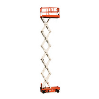
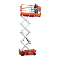
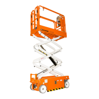
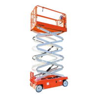
Covers S2646E/S3246E and S2646/S3246 aerial platforms, detailing model and date specificity.
Specifies that maintenance, inspection, testing, or repair must be done by qualified personnel.
Lists common abbreviations used throughout the manual for clarity and consistency.
Provides contact information for Snorkel International, Inc. for correspondence and support.
Details the information required to place an order for service or repair parts.
Lists available manuals from Snorkel for supporting their machines.
Emphasizes the user's responsibility to comply with all applicable OSHA regulations.
Exploded view and part list for chassis, steering, and brake components.
Exploded view of the pothole protector assembly with itemized parts.
Exploded view for pothole protector models manufactured after February 2011.
Exploded view and part list for battery and hydraulic trays and mounting hardware.
Exploded view of the battery tray assembly showing components and their locations.
Exploded view of battery tray for models manufactured after February 2011.
Exploded view of the hydraulic tray assembly with itemized parts.
Exploded view for hydraulic tray models manufactured after February 2011.
Exploded view and part list for the scissor stack assembly on S2646 models.
Diagrams showing components of the scissor stack for S2646E models.
Exploded view and part list for the scissor stack assembly on S3246 models.
Diagrams showing components of the scissor stack for S3246E models.
Exploded view and parts list detailing scissor stack installation.
Exploded view and parts list for the pothole actuator installation.
Exploded view of the platform assembly with itemized parts.
Exploded view and parts list for platform installation procedures.
Exploded view and parts list for step installation.
Exploded views showing locations of placards and decals for S2646 models.
Exploded views showing locations of placards and decals for S3246 models.
Introduction to the hydraulic system of the aerial platforms.
Exploded view and part list for steering, drive, and brake hoses.
Exploded view and seal kit for the steering cylinder assembly.
Exploded view and part list for drive motor hoses.
Exploded view and part list for the drive speed manifold assembly.
Exploded view and part list for the hydraulic drive motor components.
Exploded view and part list for hydraulic tray hoses.
Exploded view and part list for the main manifold valve assembly.
Exploded view and part list for the hydraulic pump assembly.
Exploded view and parts list for hydraulic hoses on S2646 scissor stack.
Exploded view and seal kit for the lift cylinder on S2646 models.
Exploded views showing hydraulic hose routing for S3246 models.
Exploded view and seal kit for the lift cylinder on S3246 models.
Introduction to the electrical system of the aerial platforms.
Exploded view and part list for chassis wiring harnesses.
Diagram and part list for the limit switch assembly.
Exploded view and part list for battery tray wiring connections.
Exploded view and part list for the US version of the battery charger.
Exploded view and part list for the AU/NZ version of the battery charger.
Wiring diagram and parts for battery tray models after September 2005.
Wiring diagram and parts for battery tray models after February 2011.
Exploded view and part list for battery charger models after September 2005.
Wiring diagram and parts list for the hydraulic tray.
Exploded view and part list for the hydraulic pump's electric motor.
Exploded view of the lower control box with component identification.
Exploded view of the lower control box for CE compliant models.
Exploded view for CE lower control box models manufactured after February 2011.
Exploded view and part list for the main wiring harness assembly.
Exploded view and wiring diagram for the GFCI electrical outlet.
Exploded view and parts list for connecting the stack harness.
Exploded view and wiring details for stack harness on S2646/S3246.
Exploded view and part list for the upper control box assembly.
Exploded view and part list for CE compliant upper control box.
Exploded view of the joystick controller assembly for the upper control box.
Exploded view and part list for internal wiring harness of the upper control box.
Exploded view and parts for ANSI compliant upper control box.
Exploded view and parts for CE/AU compliant upper control box.
Exploded view and part list for the joystick assembly.
Exploded view and parts list for the CE compliant overload system.
Diagram and part list for the CE overload system wire harness.
Introduction to optional equipment available for the aerial platforms.
Exploded view and part list for the flashing light assembly.
Exploded view and parts for key switch installation on the lower control box.
Exploded view of the upper control box with the horn option installed.
Exploded view of the upper control box with battery condition indicator option.
Exploded view of upper control box with both horn and battery indicator options.
Exploded view of CE upper control box with battery condition indicator option.
Exploded view and parts for the chain-type platform entry system.
Exploded view and parts for the gravity bar platform entry system.
Exploded view of the swing gate platform entry system.
Exploded view and parts for the lanyard attachment.
Exploded view of the battery tray designed for maintenance-free batteries.
Exploded view and parts list for the AC generator option.
Exploded view illustrating the wiring for the AC generator option.
Diagrams and parts related to Canadian Standards Association (CSA) compliance.
General information and guidelines for maintaining the aerial platform.
Preventive maintenance schedule for detecting defects and providing information.
Daily prestart inspection checklist for operators and technicians.
Inspection and maintenance tasks for every 90 days or 150 hours of operation.
Annual maintenance tasks to be performed every 500 hours of operation.
Logbook for recording details of major repair work performed on the machine.
Guidance on recommended lubricants and their application points.
Information on the hydraulic oil return filter, including replacement intervals.
Guidance on checking and maintaining batteries and their connections.
Detailed information on battery care, charging, and maintenance practices.
Information on the onboard automatic battery charger's operation and features.
Chart providing recommended torque values for various bolt grades and sizes.
Collection of electrical schematic diagrams for various machine components.
Electrical schematic diagram for the upper control box.
Electrical schematic for CE version of the upper control box.
Electrical schematic for the upper control box with horn option.
Electrical schematic for the upper control box with battery indicator option.
Electrical schematic for upper control box with horn and battery indicator options.
Electrical schematic diagram for the lower control box.
Electrical schematic for the CE version of the lower control box.
Standard US electrical schematic diagram for the machine.
US electrical schematic including horn and battery indicator options.
Standard CE electrical schematic diagram for the machine.
CE electrical schematic for models manufactured after February 2011.
Hydraulic schematic diagram illustrating the hydraulic system.
Hydraulic schematic for all machines manufactured after February 2011.
Safety instructions and warnings for using the battery charger.
Steps for operating the automatic switch-mode battery charger.
Maintenance procedures and checks for the battery charger.
Common problems, causes, and solutions for the battery charger.
Instructions for safely replacing the battery charger unit.
Technical specifications for the automatic switch-mode battery charger.
Snorkel's warranty terms and conditions for new machines.
Warranty coverage details for replacement parts.
Steps required for submitting a warranty claim.
Procedures for reporting and handling freight damage.
List of items and conditions explicitly excluded from the warranty coverage.
Schedule detailing the warranty periods for different machine components.
Contact details for Snorkel distributors in Europe, Middle East, Africa, and Asia.
Contact details for Snorkel distributors in North and South America.
Contact details for Snorkel distributors in Australia.
Contact details for Snorkel distributors in New Zealand.
| Model | S2646E |
|---|---|
| Category | Lifting Systems |
| Drive Type | Electric |
| Max Slope | 25% |
| Gradeability | 25% |
| Platform Height | 26 ft (7.9 m) |
| Working Height | 9.9 m |
| Platform Dimensions | 1.07 m x 2.44 m |
| Drive System | 2WD |
| Stowed Dimensions | 2.41 m x 1.17 m x 2.28 m |
| Ground Clearance | 0.1 m |
| Tire Type | Solid non-marking tires |