Chapter 7 – Controls
S3215L/S3215E/S3219E/S3220E/S3226E/S4726E/S4732E – 1500834 29
Movement of the joystick in a given direction produces
a corresponding movement of the aerial platform. The
steering and drive functions may be operated separately
or simultaneously.
Interlock Switch
The joystick has an interlock switch in the handle (refer
to Figure 7.3).
y Engage the interlock by grasping the joystick and
pulling the switch toward the handle.
y Engage the interlock to activate the steering, drive,
or lift functions.
Steer Switch
The steer switch (refer to Figure 7.3) is a momentary
contact, rocker switch on top of the drive joystick. This
switch controls the two front wheels to steer the aerial
platform.
y To steer to the right, engage the interlock switch on
the joystick and hold down the right side of the steer
switch.
y To steer to the left, engage the interlock switch on the
joystick and hold down the left side of the steer switch.
Note
The steering wheels are not self-centering. Set the steer-
ing wheels straight ahead after completing a turn.
Drive Range Switch
The drive range switch (refer to Figure 7.3) has two po-
sitions to select drive wheel operation:
y High (Rabbit) – for normal driving conditions
y Low (Turtle) – for driving on grades up to 25 percent
that require low speed and high torque operation, where
high range is not sucient to climb the grade.
Note
Some early model S3219E and S3220E machines were
not equipped with a drive range switch.
Horn Button
The horn button (refer to Figure 7.3) is on the front of the
upper control panel.
Press the button to sound the horn.
Battery Condition Indicator
The battery condition indicator (refer to Figure 7.3) is
located on the top of the upper control panel. When the
light comes on, the lift function is cut out and drive speed
is reduced to slow.
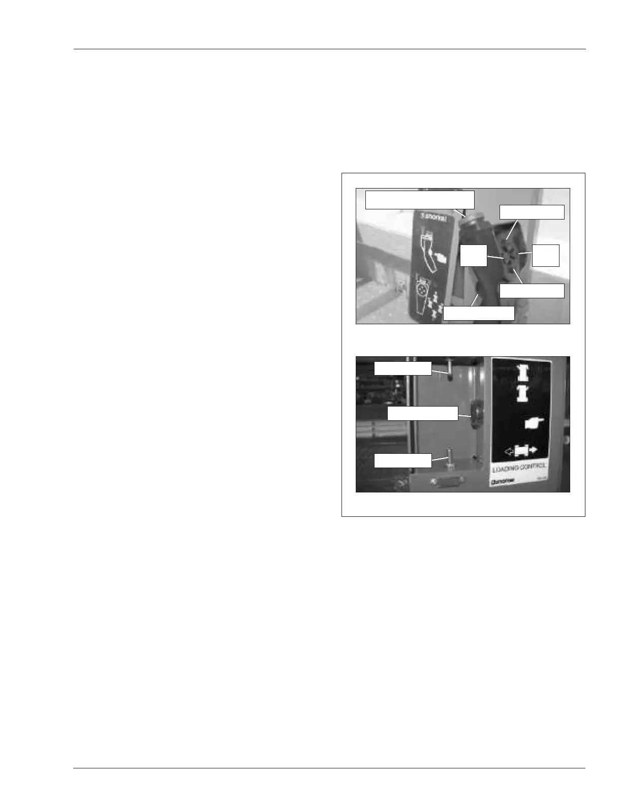
Loading Controls
The loading controls are located beneath the upper
control box on the platform guardrail. Drive functions
may be operated from this location when loading the
machine. The loading controls may be a xed side drive
or a corded pendant (refer to Figure 7.4). Pull the upper
control emergency stop button outward to activate the
loading controls.
Figure 7.4 – Loading Controls
The following are located on the loading controls:
y Emergency stop button – pendant only
y Interlock button
y Drive forward/reverse control
y Steer left/right control
Emergency Stop Button
The emergency stop (refer to Figure 7.4) is a two-position,
red push button on the top of the pendant.
y Push the button inward to disconnect power from the
pendant.
y Pull the button outward to restore power.
y Push the emergency stop button inward when the
pendant is not in use to protect against uninten-
tional operation.
Pendant
Fixed Side Drive
Interlock Button
Drive Switch
Steer Switch
Drive Forward
Steer
Left
Emergency Stop Button
Interlock Button
Drive Reverse
Steer
Right