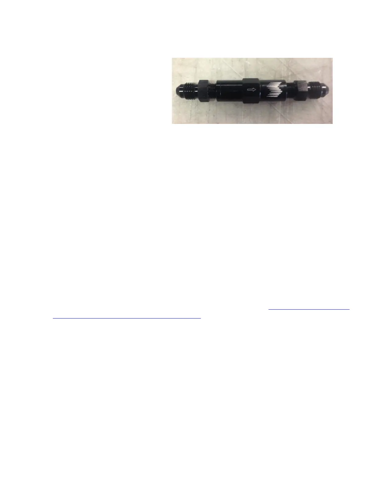
Braided line kits - Fit the NPT thread to
4AN adapters in each side of the check
valve using E-6000 sealant on the NPT
threads only. Connect the 5 foot section of
braided line from the pump outlet to check
valve inlet and the 1’ or 2’ section of
braided line from the check valve outlet to
the nozzle holder inlet.
When running the high pressure tubing or braided line from the in line check valve to the nozzle holder location,
care should be taken to avoid extreme heat such as exhaust manifolds as well as any area that may abrade the line
due to engine vibration and torque over. Also, ensure the lines are clear of the serpentine belt system.
Step 6
Unit Wiring (Wiring Diagram on page 8)
Connect the Red and Black pump wires to the corresponding Red and Black wires on the controller’s MAIN
Pump output harness.
Connect the MAP sensor. DO NOT use the RED wire if TEEing into the factory MAP sensor wiring.
Connect the ORANGE wire to a switched 12V IGN source that is hot in Accessory, Start and Run
Connect the YELLOW wire to a clean (noise-free) 0-5V or 0-12V square wave RPM signal source. On some
vehicles this signal is available from the engine computer (like certain Ford models or nearly all BMW
models). On other vehicles this signal should be taken from the output of the CAMshaft position sensor only
if the sensor is a 3-wire Hall-Effect type. CRANKshaft sensor should not be used and 2-wire (inductive)
sensors cannot be used. On other vehicles the low-voltage 5V trigger signal between the engine computer
and the coil-on-plug module on CYL 1 can be used or the connection between the engine computer and the
CYL 1 injector, although these two options often result in noisy readings where the RPM signal is erratic. In
some cases, the only way is a 3
rd
party CANBus to RPM converter like CANM8 (http://www.canm8.com/can-
bus-interfaces/rpm-pulse-interfaces/canm8-rpm.html) – DO NOT USE any other module that receives data
through the OBD-II port. RPM readings obtained through the OBD-II port are too slowly updated to be
useful for real-time water methanol injection.
Connect the heavy gauge BLACK wire from the controller’s BATTERY power harness to a clean vehicle
chassis ground connection closes to the controller. Try to locate a factory ground point (usually a threaded
stud) that is used for factory wire grounding in the vehicle.
Connect the heavy gauge RED wire to the car’s +12V battery terminal through a 40A inline fuse installed
RIGHT AT THE BATTERY. DO NOT INSTALL WITHOUT A FUSE.