The small rubber-banded loop in right ascension sensor cable shown in Figure 8 is intended to provide
strain relief. This loop can also be used to attach the zip. The pointed, non-looped end of the zip tie
should be fed up through the mount, to the sensor connectors. There are two holes in the base of the
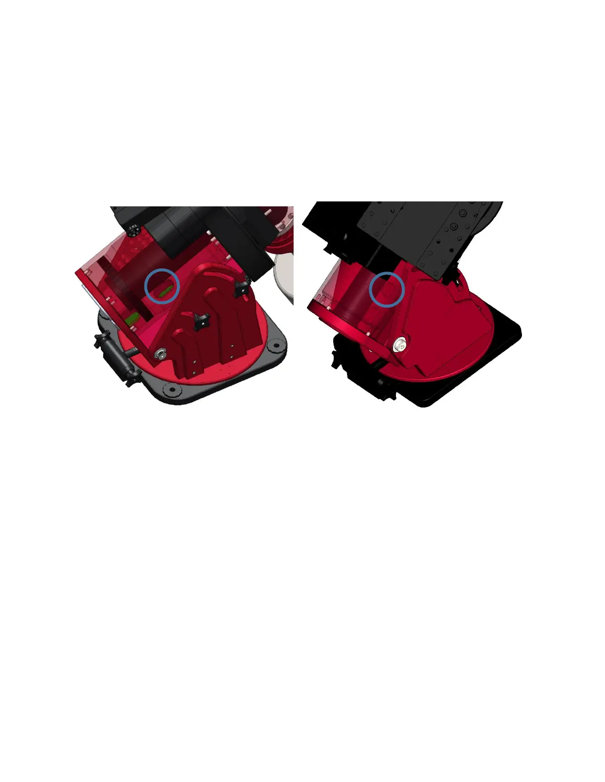
right ascension axis for both the Paramount ME II and Paramount MX/MX+ (Figure 11). The right
ascension sensor cable must be fed through the hole, located toward the center of the mount and is
circled in blue in Figure 11 for the Paramount ME II and Paramount MX/MX+. For the Paramount MYT
there is only one hole in the RA base used for all cables coming from the electronics box, see Figure 12.
Figure 11: RA base, RA wiring hole (Paramount ME II on the left, Paramount MX/MX+ on the right).