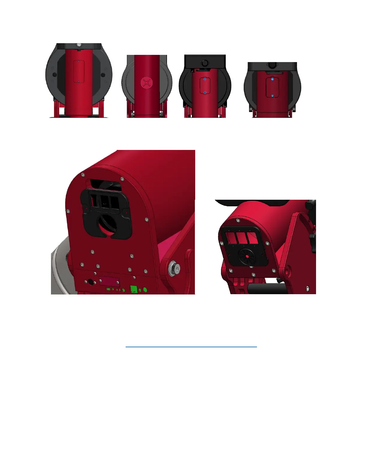
Figure 9: Declination axis hole cover with screws.
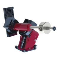
(From left to right Paramount ME II, Paramount MX, Paramount MX+, Paramount MYT)
Figure 10: Right ascension rear cover.
Removing the Electronics Box
Please refer to this document: http://www.bisque.com/sc/media/p/63292.aspx. It also explains the
purpose of each cable plugged in to the MSK 5000 board. Depending on how small and nimble your
hands are, it is probably easiest to unplug all of the cables and completely remove the Electronic Box
before removing and replacing the homing sensor cable.
Installing the Replacement Homing Sensor Cable
The Paramount Accessory Kit includes a long zip tie looped at one end. This tie is especially helpful to
install the replacement cable. Use a short piece of electrical tape to attach the connector to the looped
end of the zip tie.