Testing RM2L-NH Keypads
15
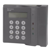
TESTING RM2L-NH
KEYPADS
To test RM2L-NH keypads:
1. Properly configure Devices, Inputs, and Outputs using the C•CURE Administration
application and put the device Online.
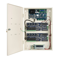
2. Measure the supply voltage to the RM-4.
The voltage can be measured between pin 1 (+12 VDC supply) and pin 4 (ground)
on the P4 connector. The voltage must be +12 VDC (+/-5%).
3. Check the RM2L-NH device address setting.
The RM2L-NH device must be set to an unused address, between 1 and 8, when
connected to the apC or iSTAR. Use rotary switch SW1 to set the device address.
4. Check the RM-4 for communications to the apC or iSTAR by observing LED2 and
LED3.
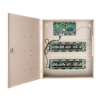
5. Check the supervised inputs. Configure the inputs on the apC or iSTAR using the
C•CURE Administration application.
With no switches or resistors connected to the supervised input 1 and 2 lines, the
C•CURE Monitoring application should report inputs as “Open Loop”. When you
connect the 1,000-ohm resistor to the input terminals, the C• CURE Monitoring
application should report that the input as “Deactivated”. Supervised inputs #1 is
found at pins 4 and 5 of P5. Supervised input #2 is found at pins 6 and 7 of P5.
6. Check the outputs.
The outputs can be functionally tested by using the “momentary activate” feature in
the C• CURE Monitoring application. When the outputs are momentarily activated,
the signal will change state for a few seconds.