Home
Solar-Log
Measuring Instruments
1200
Solar-Log 1200 Installation Manual
5
of 1
of 1 rating
224 pages
Give review
Manual
Specs
To Next Page
To Next Page
To Previous Page
To Previous Page
Loading...
19
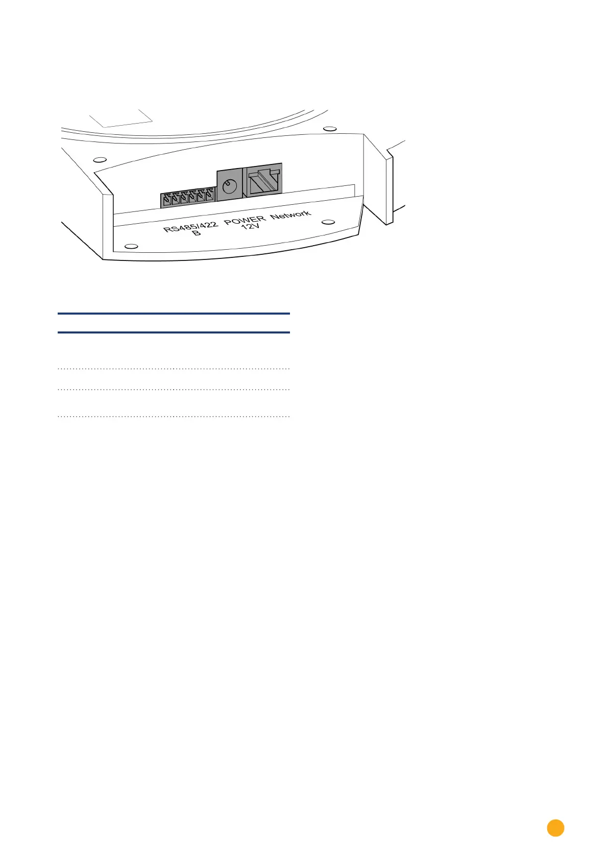
Unit connections
Bottom c
onnections
Fig.: Bottom connections Solar-Log 300
Solar-Log 300 / Solar-Log 250
RS485/422 - B
RS485 interface, 6 pin:
Connection for inverters
and additional accessories
Power 12 V
12 volt DC input
Network
Ethernet network interface,
10/100 Mbit
18
20
Table of Contents
Table of Contents
3
Introduction
9
Notes for the Firmware Update
10
Updating from Firmware 2.X to 3.X
11
Safety Information
12
Target Group for this Manual
12
Hazard Classes
13
Electric Current
14
Package Contents
15
Fig.: Solar-Log™ Wall Mounting
16
Wall Mounting
16
Unit Connections
18
Solar-Log 300 / Solar-Log 250
18
Solar-Log 1200
20
Fig.: Top Connections Solar-Log 1200
20
Solar-Log 2000
22
Fig.: Top Connections Solar-Log 2000
22
Fig.: Antenna Connection on the Top of the Device (Solar-Log™ GPRS)
24
Optional Connections
24
Fig.: Insertion Slot for SIM Card Inside on the Right (Solar-Log™ GPRS)
24
Solar-Log™ GPRS
24
Solar-Log™ Meter (Solar-Log 300 and 1200)
25
Fig.: Connection for Current Transformers (Solar-Log™ Meter)
25
Fig.: Two 6-Pin Terminal Block Connectors for the Meter Interface
26
Solar-Log™ PM
28
Fig.: 6-Pin PM+ Interface
28
Connector Assignments and Wiring
29
Notes on Wiring the Connections
29
Fig.: Example Wiring on a 4-Pin Terminal Block Connector
29
RS485-A (Only Solar-Log 1000, 1200 and 2000)
30
Fig.: Terminal Block Connector with Ferrules
30
Fig.: 4-Pin Terminal Block Connector
30
Rs485/422 - B
31
Fig.: 6-Pin Terminal Block Connector
31
RS485/422 - C (Only Solar-Log 2000)
32
S0 out in (S0-OUT and S0-IN)
33
Fig.: Schematic Diagram of the S0 Output
33
S0-In
34
Fig.: 4-Pin Terminal Block Connector
35
Fig.: 6-Pin PM+ Interface
35
Connecting the Inverters
36
Switch off the Inverters and the Solar-Log
37
Sensor Box Basic and Professional
38
Connecting Accessories
38
Sensor Box Professional Plus
40
Fig.: Mounting Information for the Sensor Box Professional Plus
40
Ripple Control Receiver
43
Fig.: 6-Pin PM+ Interface
43
Fig.: the Basic Principle of Wiring the PM+ Interface to the Ripple Control Receiver for Active Power Commands
43
Large External Displays
44
External Power Meter
46
Wiring for S0 Meter
48
Wiring for RS485 Meter
50
Installation Utility Meter / Janitza UMG 104 (Only Solar-Log 1000 and 2000)
53
Fig.: Utility Meter Connection Diagram for Voltage Measurements in Low-Voltage Power Grids
54
Fig.: Utility Meter Connection Diagram for Current Measurements with Current Transformers
55
Solar-Log™ Smart Relay Box
57
Fig.: Smart Relay Box Relay Output (Change-Over Contact) Diagram
58
Fig.: Smart Relay Box Relay Output (Make Contact) Diagram
58
Wemo Insight Switch
59
Allnet Network Power Socket
60
Other Connections
62
Alarm Contact (Only Solar-Log 1000 and 2000)
62
Fig.: Alarm Contact Connection Diagram
62
Relay (Only Solar-Log 1000, 1200 and 2000)
63
Fig.: Relay Connection Diagram
63
Usb
64
Installation
65
Connecting the Solar-Log™ to a Network / PC
65
Initial Installation Solar-Log 200, 250 and 300
66
Instructions for Connection through the Powerline Package
66
Carrying out the Initial Set up of the Solar-Log 200, 250 and 300
67
Initial Set up of the Solar-Log 1200
67
Carrying out the Initial Set up of the Solar-Log 1200
68
Initial Installation Solar-Log 1000 and 2000
68
Carrying out the Initial Set up of the Solar-Log 2000
68
Starting the Configuration
69
Fig.: Main Menu of the Solar-Log 2000 PM+ GPRS
69
Fig.: Solar-Log™ Model Tag
70
Using the Browser Menu
71
Fig.: Layout of the Main Menu
71
Fig.: Control Elements in the Browser Menu
72
Main Menu
73
Configuration Menu
74
Configuring Network Settings
74
Fig.: Ethernet Settings
75
Ethernet
75
GPRS (Only Solar-Log™ GPRS)
76
Fig.: GPRS Settings
76
General Information about GPRS Devices
79
Wifi (Only Solar-Log Wifi)
80
Fig.: Wifi Settings
80
Proxy
82
Fig.: Proxy Settings
82
Portal
83
Internet Configuration
83
Access Type
83
E-Mail
84
Text Message (SMS)
85
Fig.: Example Configuration STATTLS to Send E-Mail with GMX
85
Export
86
Backup
86
Configuring the Device Interface
87
Fig.: Interface Definition Via the Plus Symbol
87
Device Definition
87
Configuring Connected Devices
87
Fig.: Adding Components
88
Fig.: Overview of the Selected Components
89
Defining the Solar-Log™ Meter (Only Solar-Log™ Meter)
90
Fig.: Device Definition for the Solar-Log™ Meter
90
Fig.: Solar-Log™ Meter Operating Mode
92
Device Detection
93
Fig.: Device Detection - Not Started yet
93
Configuring Devices
94
Configuring Inverters
94
Configuring Power Meters
95
Configuring Sensors
96
Module Fields, Power Output and Descriptions
96
Configuring EGO Smart Heaters
97
Configuring IDM Heat Pumps
98
Keba-Stromladestation Konfigurieren
99
Fig.: Example of the Module Field Division
101
Changing the Device Order
101
Module Fields
101
Battery
102
Fig.: Battery Configuration with Help Text
102
Configuring Plant Data
103
General
103
Plant Groups
104
Graphic
104
Defining the PV Plant's Forecast Data
105
Defining the Feed-In Tariff
106
Fig.: Tariff - Tariff Settings
107
Configuring Notifications
109
Recipient
109
Device Notifications
110
Fig.: Status and Fault Code Groups
110
Yield
112
Fig.: Configuration Example for Filtering Status and Fault Codes
112
Alarm (Only Solar-Log 1000 and 2000)
113
Power & Failure
113
Initial Yield
116
Editing Data
116
Data Correction
117
System Backup
117
Backup
119
Reset
121
System Configuration
123
Access Control
123
Language/Country/Time
124
Fig.: Configuring the Time on the Solar-Log
124
Display
126
Licenses
127
Firmware
127
Smart Energy
130
Defining Smart Energy Switching
130
Fig.: Selecting Switch for Smart Energy
130
Smart Energy Switching Groups
131
Fig.: Creating Switching Groups
132
Creating Switching Groups
132
Fig.: Adjustable Switch with Help Text
134
Configuring Switching Groups
135
Fig.: Control Logic Configuration Window
135
Smart Energy Surplus Management
141
Fig.: Surplus Management
141
Feed-In Management
143
Plant Parameters
143
Fig.: Configuration of UC and uns at Different Voltage Levels
143
Active Power
145
Active Power Deactivated
146
Remote Controlled Active Power Reduction (Only Solar-Log™ PM+)
146
Fig.: Schematic Diagram of a Ripple Control Receiver with Four Relays
147
Fig.: Channel Settings for Power Reduction
148
Remote Controlled Active Power Reduction with the Calculation of Self-Consumption
149
Log™ PM+)
149
70% Fixed Reduction
149
70% Fixed Reduction with the Calculation of Self-Consumption
150
Adjustable Reduction
151
Adjustable Reduction with the Calculation of Self-Consumption
151
Fixed Reduction in Watts
152
Fixed Reduction in Watts with the Calculation of Self-Consumption
152
Percentage of Consumption for an Adjustable Reduction
152
Reactive Power
153
Reactive Power Deactivated
153
Fixed Value Cos (Phi) Shift Factor
154
Fixed Reactive Power in Var
154
Variable Cos (Phi) Shift Factor over Characteristic Curve P/Pn
156
Variable Reactive Power Via the Characteristic Curve Q(U)
157
(Only Solar-Log 2000 with Utility Meter)
157
Fig.: Q(U) Control Function Diagram
157
Remote-Controlled Fixed Value Cos (Phi) Shift Factor Only Solar-Log™ PM+)
159
Fig.: Schematic Diagram of a Ripple Control Receiver with Four Relays
159
Fig.: Channel Settings for Remote Controlled Cos (Phi)
160
Fig.: Switching to Reactive Power Characteristic Curves with Certain Signals
160
Fig.: Solar-Log™ Network Configuration
161
Linking (Only Solar-Log 1000 and 2000)
161
Profile
162
Fig.: Activated PM+ Profile for a PM Package
162
Direct Marketing
164
Direct Device Configurations
166
(Solar-Log 1200 and 2000)
166
Display Menu Structure
166
Fig.: Display: Energy Balance
167
Start Menu (Only Solar-Log1200)
167
Settings on the Device
167
Control Elements on the Display
167
Initial Configuration (Only Solar-Log 1200)
168
Fig.: Display: Initial Configuration Language Selection
168
Fig.: Display: IP Address Settings in the Initial Configuration
168
Fig.: Initial Configuration - Device Selection
169
Fig.: Device Classes - Definition
169
Fig.: Inverter Selection
170
Fig.: Interface Definition
170
Fig.: Inquary about a Connected Wireless Package
171
Fig.: Configuring the Baud Rate
171
Device Detection (Only Solar-Log 1200)
172
Fig.: Display: Device Detection
172
Fig.: LCD: Number of Detected Inverters
172
Easy Installation (Only Solar-Log 1200)
173
Fig.: Display: Start Easy Installation
173
Basic Settings Menu
174
Basic Settings | Network Menu
174
Fig.: Network Settings Page1 on Solar-Log 1200 Display
174
Basic Settings | Portal Menu
175
USB Menu
175
Advanced Settings Menu
177
Fig.: Display Brightness
178
Fig.: Slide Show Dialog
178
Fig.: Display Access Control
179
Fig.: System Settings - Initialize Yield Data
179
Fig.: Language Selection
180
Fig.: Display Firmware
180
Fig.: Country Settings
181
Error and Fault Messages on the Display
182
Fig.: Tachometer - with a Warning (Red Triangle) in the Top Line
182
Fig.: Loaded Notifications
182
Notifications on the LCD Status Display
183
Meaning of the Symbols on the LCD Display
183
Fig.: LCD Display - All Symbols Active
183
Fig.: LCD Display - Meaning of the Symbols
184
Fault Messages
185
Fig.: Blinking Internet Symbol
185
Notifications on the LCD Display
186
Normal Operation
186
Power Reduction
186
Fig.: LCD Display During Normal Operation
186
Fig.: Display 70% Fixed Reduction
186
Fig.: Reset Buttons
187
Reset
187
Reset Buttons
187
Restarting and Resetting
187
Faults
187
Restoring the Factory Settings
188
Rebooting and Resetting Via the Web Menu
189
Fault Messages
190
Fault Messages GPRS
190
Fault Messages Time
191
Fault Messages Wifi
191
Fault Messages Internet
192
Fault Messages Export to External Server and Backup
193
Fault Message E-Mail Transfer
195
Portal Transfer Fault Messages
197
Fault Messages Feed-In Management
197
Special Cases
198
Disposal
199
Technical Data
200
Internet Ports
204
Appendix
204
Country Specific Inverter Detection with Easy Installation
205
Wiring Meters to Record Self-Consumption
206
Meter Connection Options to Record the Total Consumption Via an RS485/S0 Interface
206
Fig.: Wiring Diagram for Recording Self-Consumption
206
Meter Connection Options for Bi-Directional Recording of the Total Consumption Via Only an RS485 Interface
207
Connection Examples for Ripple Control Receivers
208
Variation with 4 Relays (ENBW >100Kwp)
209
Variation with Two Relays
211
Variation with Three Relays
213
Variation with 5 Relays (Including Emergency Stop)
215
Digital Interfaces
217
Modbus TCP
217
Live Data Compact - Summarized (Complete Plant)
218
JSON Interfaces
219
Dimensions
221
List of Figures 32 List of Figures
222
List of Figures
222
Other manuals for Solar-Log 1200
Manual
319 pages
User Manual
158 pages
Connection Manual
24 pages
5
Based on 1 rating
Ask a question
Give review
Questions and Answers:
Need help?
Do you have a question about the Solar-Log 1200 and is the answer not in the manual?
Ask a question
Solar-Log 1200 Specifications
General
Brand
Solar-Log
Model
1200
Category
Measuring Instruments
Language
English
Related product manuals
Solar-Log 200
319 pages
Solar-Log 300
158 pages
Solar-Log 2000
319 pages
Solar-Log PRO380-CT
4 pages
Solar-Log Pro 380
4 pages
Solar-Log 500
319 pages
Solar-Log 250
319 pages
 Loading...