43
Connecting accessories
12.3 Ripple Control Receiver
The Solar-Log™ PM+ series contains an additional 6-pin interface which allows up to two ripple control
receivers or telecontrol plants each with four signals to be connected.
Wiring
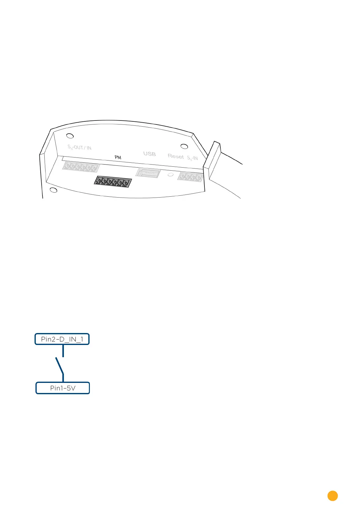
The relay contacts for the ripple control receiver are connected to the Solar-Log™ PM+ via the 6 pin PM+
interface on the top side of the Solar-Log™.
Fig.: 6-pin PM+ interface
The ripple control receivers used by grid operators utilize various numbers of relays. These relays are la-
beled differently and have different reduction levels and/or shift factors cos (Phi).
To ensure the highest degree of flexibility, the reduction levels specified by the grid operators, together
with their signals from the ripple control receiver, can be evaluated by the Solar-Log™ via a maximum of
four digital inputs for each.
In order that the Solar-Log™ PM+ can evaluate the signal from the ripple control receiver, it needs to be
wired to the control voltage (for active and reactive power) from the PM+ interface. The control contracts
normally operate as make contracts; that means they are closed for the respective command.
The control voltage from Pin 1 is used for the active power command.
The control voltage from Pin 6 is used for the reactive power command.
The control voltage is connected to the common contact of each relay. The relay output (closed contact)
is then connected to a digital input of the PM+ interface.
Fig.: The basic principle of wiring the PM+ interface to the ripple control receiver for active power commands
See the Appendix for more ripple control receiver connection examples on page of this installation
manual.
Further configurations of feed-in management are carried out via the Solar-Log™ PM+ web interface in the
Configuration | Feed-in Management menu with the Active Power | Remote-controlled and Reactive
Power | Remote-controlled shift factor cos(Phi) functions. See Seite 143for more information.
 Loading...