209
Appendix
31.4.1 Variation with 4 relays (ENBW >100kWp)
Specifications
Ripple control receiver signals
Level K1 K2 K3 K4 Power out-
put
1 On Off Off Off 100%
2 Off On Off Off 60%
3 Off Off On Off 30%
4 Off Off Off On 0%
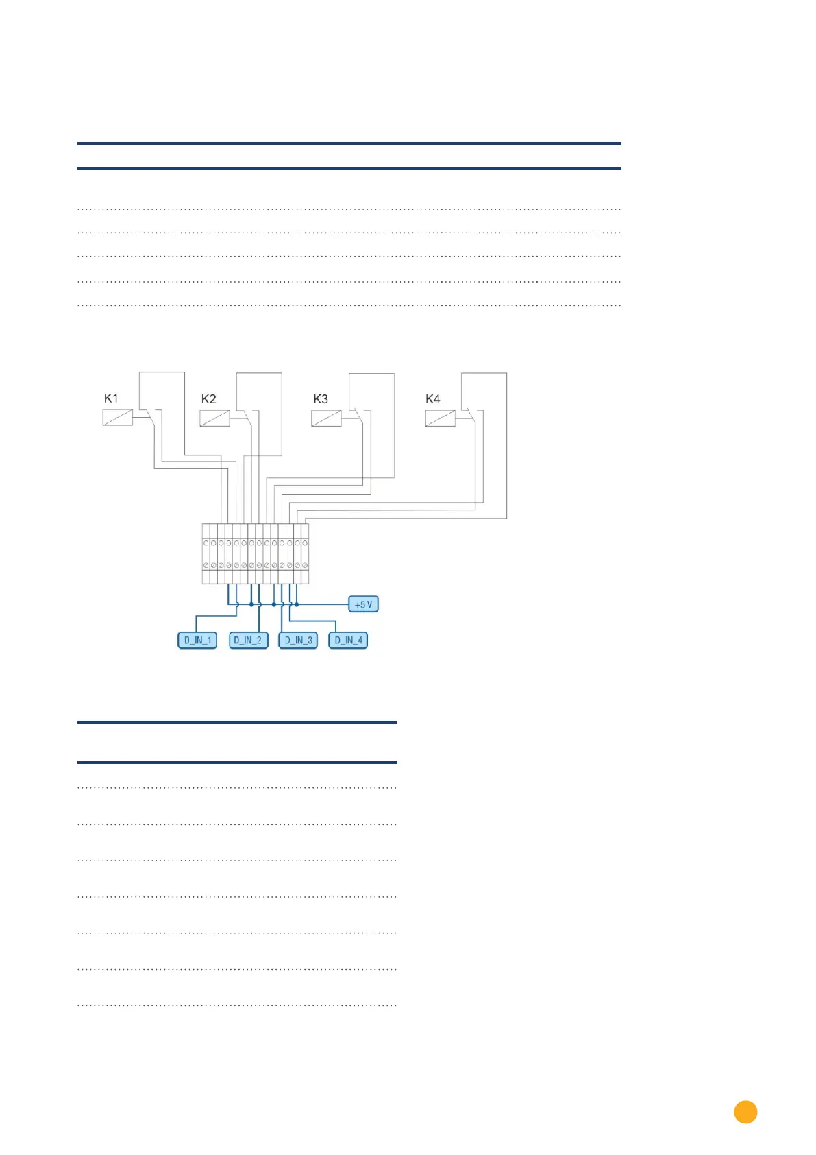
Wiring
Fig.: Wiring a ripple control receive with two relays - example 1
Connecting PM+ terminal connector
and ripple control receiver
PIN Assignment Meaning
1 +5V Control voltage for active
power
2 D_IN_1 Level 1
100%
3 D_In_2 Level 2
60%
4 D_In_3 Level 3
30%
5 D_In_4 Level 4
0%
6 +5V Control voltage for reac-
tive power (unused)
 Loading...