NOTE
Do not cross-connect B, A and G wires.
11. Tighten the terminal block screws.
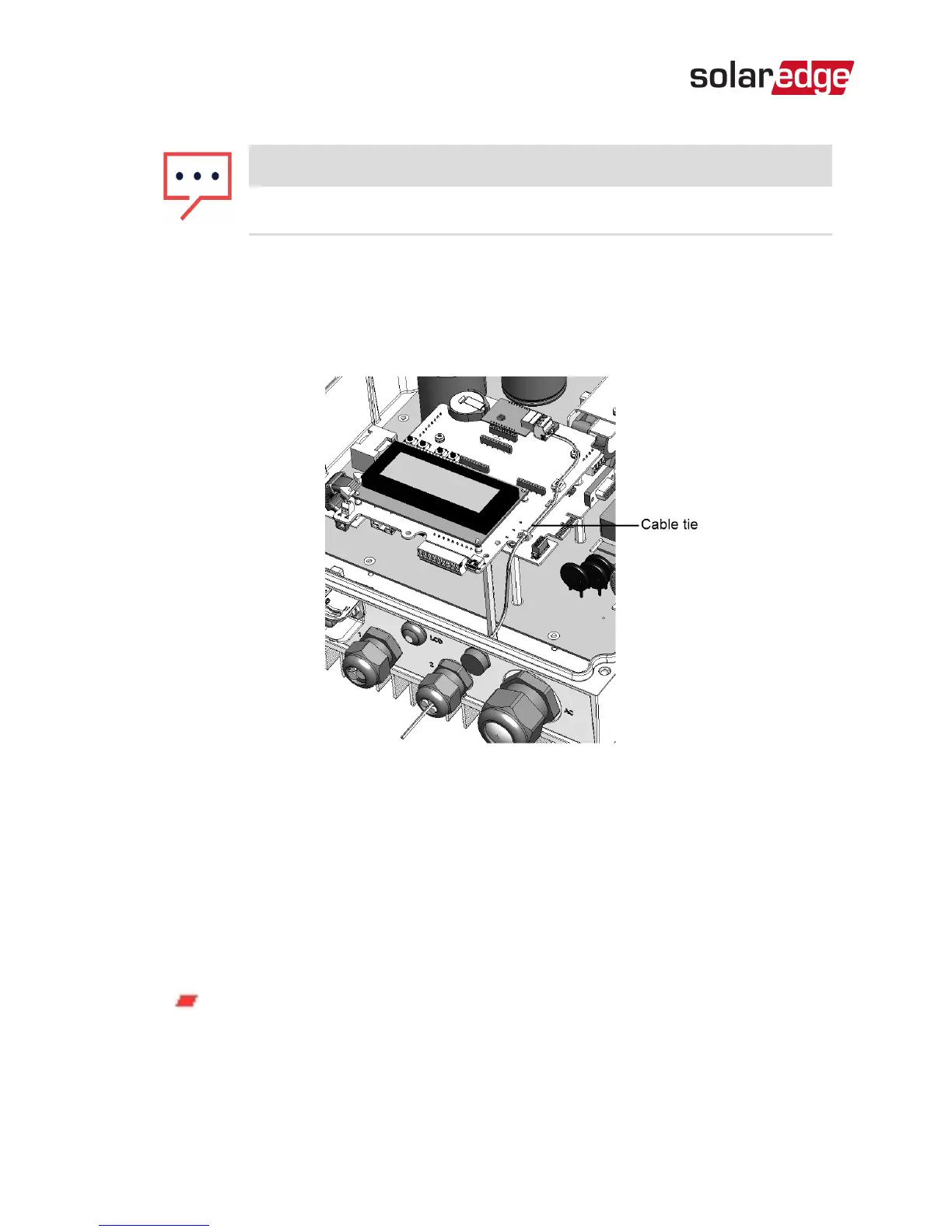
12.
Tighten the cable to the communication board using the
cable tie.
Figure 7: RS485 cable connected
13. Check that the wires are fully inserted and cannot be pulled
out easily.
14.
Terminate the first and last devices in the chain by
switching a termination DIP-switch to ON:
RS485 Expansion Kit Installation Guide MAN-01-00258-1.0
13 Installing the RS485 Module
The inverter that contains the expansion module
should be terminated by switching ONthe
DIPswitch on the module.