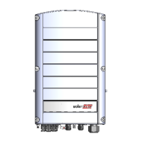
Figure 5: RS485 3-pin terminal block
9. Insert the wire ends into the G, A and B pins shown above.
Use four- or six-wire twisted pair cable for this connection.
You can use any color wire for each of the A, B and G
connections, as long as the same color wire is used for all A
pins, the same color for all B pins and the same color for all
G pins.
10.
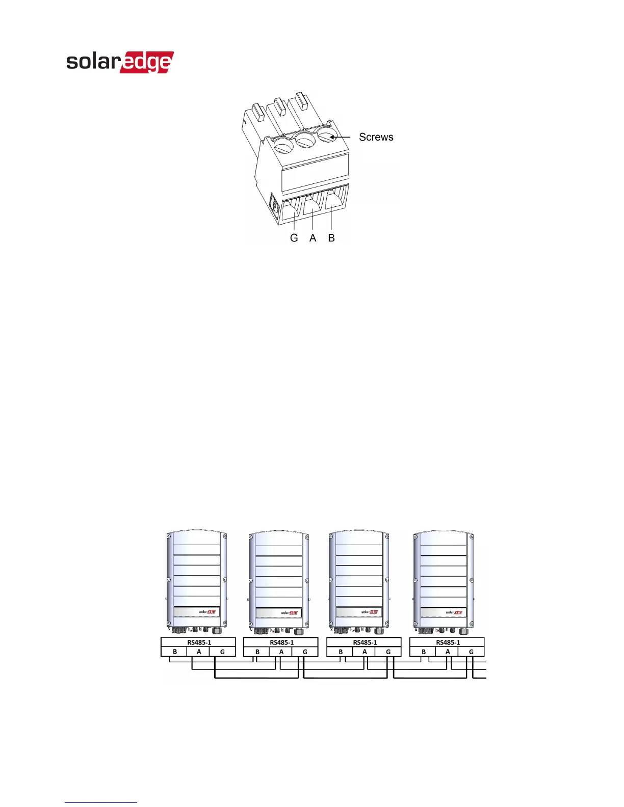
For creating an RS485 bus - connect all B, A and G pins in
all the devices. The following figure shows this connection
scheme when connecting a bus of inverters:
Figure 6: Connecting the inverters in a bus
RS485 Expansion Kit Installation Guide MAN-01-00258-1.0
Chapter 2: Installation 12